
This design takes up board space and is relatively expensive, tending to offset the advantages of the integrated device. An alternative possibility is to boost the output drive capability by connecting opamps in parallel. The output current will then be approximately proportional to the number of opamps. Instead of a single opamp a dual or quad device is used to achieve greater output power.

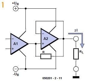
The idea is shown in Figure 1. The output of the first opamp is connected to the input of a further noninverting opamp stage as well as being connected to the output of the circuit via a resistor. The first opamp thus drives the second non-inverting amplifier which provides all the output current of the circuit as long as that remains within its normal capability.
As the output current demand increases the second opamp will reach the limit of its drive capability. Its gain will then fall off and a voltage difference will develop across its inputs. The first opamp will then start to deliver more and more current to the output via the resistor, and the sum of the output currents of the two opamps thus flows through load resistor RL.
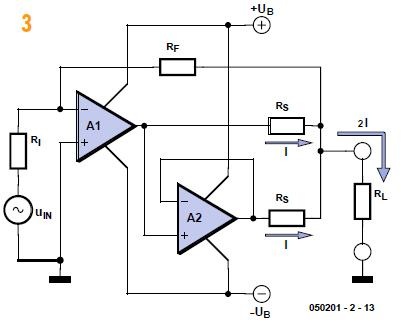
By adding another resistor we can compare the current contributions from the two opamps (Figure 2). The complete circuit with two opamps is shown in Figure 3. The principle of the circuit can be extended to more opamps with their output currents being added together (see Figure 4).
![u060373-2-14[3]](https://blogger.googleusercontent.com/img/b/R29vZ2xl/AVvXsEjUUloeuttrz7oBuH2qFGuk3v-C9Cys85gsi8mIR2p0ziLkqd7Rks18V9-eeIcl0-zpLPRg0OvtezfMw7hqCJXlPjLGnXCjk7jh4g1hWPjMdHd1AP9j5R1TQXPzRtrDVAlaEApbtj4gECKL/?imgmax=800 "u060373-2-14[3]")
Author: Klemens Viernickel
(Elektor Electronics Magazine – 2006)
 | * Download this article. |
ICs that in the past were far too expensive for the hobbyist tend to be more favorably priced these days. An example of this is the AD8099 from Analog Devices. This opamp is available for only a few pounds. The AD8099 is a very fast opamp (1600 V/ms) and has high-impedance inputs with low input capacitance.
The bandwidth of the opamp is so large that at 100 MHz it still has a gain of nearly 40. This means that this opamp can be used to create an RC oscillator. The circuit presented here realises that.
The circuit has a few striking characteristics. Firstly, unlike normal oscillators that contain transistors this one does not have any inductors. Secondly, there is no need for a varicap diode to do the FM modulation.
The opamp is configured as a Schmitt trigger with only a small amount of hysteresis. The output is fed back via an RC circuit. In this way, the trimmer capacitor is continually being charged and discharged when the voltage reaches the hysteresis threshold. The output continually toggles as a consequence. This results in a square wave output voltage. With a 10-pF trimmer capacitor the frequency can be adjusted into the VHF FM broadcast band 88-108 MHz). The frequency of the oscillator is stable enough for this. The output voltage is about 6 Vpp at a power supply voltage of 9 V. The transmitter power amounts to about 50 mW at a load of 50 Ω. This is about 20 times as much as the average oscillator with a transistor.
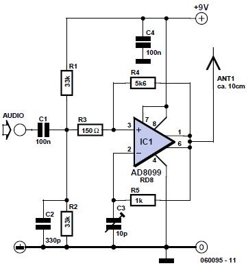
The FM modulation is achieved by modulating the hysteresis, which influences the oscillator frequency. An audio signal of about 20 mVpp is sufficient for a reasonable output amplitude.
The package for the opamp is an 8-pin SOIC (provided you use the version with the RD8 suffix). The distance between the pins on this package is 1/20 inch (1.27 mm). This is still quite easy to solder with descent tools. If SMD parts are used for the other components as well then the circuit can be made very small. If necessary, a single transistor can be added to the circuit to act as microphone amplifier. The power supply voltage may not be higher than 12 V, because the IC cannot withstand that. The current consumption at 9 V is only 15 mA.
As with all free-running oscillator circuits, the output frequency of this specimen is also sensitive to variations of the power supply voltage. For optimum stability, a power supply voltage regulator is essential.
As an additional design tip for this circuit, we show an application as VCO for, for example, a
PLL circuit. When the trimmer capacitor is replaced with a varicap diode, the frequency range can be greater than that of an LC oscillator. That’s because with an LC-oscillator the range is proportional to the square root of the capacitance ratio. With an RC oscillator the range is equal to the entire capacitance ratio. For example: with a capacitance ratio of 1:9, an LC oscillator can be tuned over a range of 1:3. With an RC oscillator this is 1:9. For the second tip, we note that the circuit can provide sufficient power to drive a diode mixer (such as a SBL-1) directly. This type of mixer requires a local oscillator signal with a power from 5 to 10 mW and as already noted, this oscillator can deliver 50 mW. A simple attenuator with a couple of resistors is sufficient in this case to adapt the two to each other.
Author: Gert Baars
(Elektor Electronics Magazine – /2006)

- Download this article.
Quartz crystals have the property that their amplitude/phase characteristic repeats itself at frequencies that are an uneven multiple of the fundamental frequency. There are so-called overtone crystals that are cut in such a manner that they possess this property to a greater extent. However, in principle, any crystal may be used on one or more of its harmonic frequencies. Harmonic generators based on transistors may operate satisfactorily on the 3rd harmonic, but if the 5th or 7th harmonic are wanted, the circuit becomes less reliable and requires frequent adjustment.
![060147[3]](https://blogger.googleusercontent.com/img/b/R29vZ2xl/AVvXsEhOBriLoAkvhSyZMt41ZfCD7fjn6UFWAPB58zF4geMfHo_rQNCOSHMJ11hcX_IdFWFafpkPfXARId2AxHJlVZw0ss6BXqFHVUTq_iyBGJy9MNnCGjv370EzeyUfxIVGi0vfF_JAjf4AyDXm/?imgmax=800 "060147[3]")
This circuit is based on a single, fast opamp and oscillates readily at the 3rd, 5th or 7th harmonic. The opamp is set up as a non-inverting amplifier with the quartz crystal connected between its output and the non-inverting input. The circuit amplification, which in principle must be unity to ensure oscillation, is determined by the network formed by R4, R5 and trimmer capacitor C3. This network is frequency-dependent such that the amplification increases as the frequency rises. The network gain is adjustable with C3. The setting of the capacitor must be such that the gain is too small for oscillation at the fundamental frequency, but sufficient for, say, the 5th or 7th harmonic.
The author uses a standard computer crystal of 10 MHz. Depending on the setting of C3, the circuit provides a stable output at frequencies between 50 and 70 MHz. It should be noted that these frequencies are multiples of the series fundamental frequency of the crystal. Tuning is carried out simply with a frequency counter. The output frequency is varied with C3. When the capacitor is roughly at the correct setting, the frequency ‘locks’ as it were at the harmonic. The area where locking occurs is not well-defined, however, so that the setting of C3 is not critical. When tuning is completed, the output frequency is crystal-stable.
In principle, the circuit may be used for frequencies of up to 100 MHz, when the values of R4 and R5 may need to be reduced. When a crystal with a higher fundamental frequency, say, 15 MHz, is used, the circuit may be tuned to the 3rd harmonic, that is, 45 MHz.
The circuit should be tested with a supply voltage of 5–9 V (the maximum supply voltage for the IC is 12 V).
The peak to peak output voltage has a value of about that of the supply voltage less a few volts. The output can provide a current sufficient to drive relatively low impedance loads.
Author: Gert Baars
(Elektor Electronics Magazine – 07/2006)
| | Download this article (direct link #060147-uk.pdf) |
