
It’s good fun to keep an eye on all sorts of things in your environment and on the basis of events in this environment to switch, for example, lamps or buzzers. To help with this, the light barrier described here can be used to guard an entrance. You can use it to signal of
someone is walking through the corridor, or to check if the car has been parked far enough in the garage to be able to close the door. The circuit consists of a transmitter, which sends modulated infrared light and a receiver, which recognizes this. The circuit used here is almost insensitive to daylight or fluorescent light and therefore can be used outside.

The transmitter (Figure 1) generates about 1000 times per second, for a period of 540 ms, a burst of 36 kHz. IC1 has been set with C1, R1 and R2 to a frequency of about 1000 Hz. The output of IC1 ensures that IC2 will oscillate about 1000 times per second for a period of about 540 ms. IC2 is set to a frequency of 36 kHz with C2, P1, R4 and R5. The output of IC2 drives the IR LED D1 via transistor T1. C3 and R3 prevent the reasonably high current through D1 from generating too much interference on the power supply rail.

The receiver (Figure 2) is quite a simple design, because IC3 already does a lot of the work for us. When the IC ‘sees’ an IR signal with a frequency of 36 kHz, the output of IC3 will become ‘0’. The transmitter circuit alternates between sending an IR-signal of 36 kHz for 540 ms and is quiet for 470 ms. When this signal arrives at IC3, C4 will discharge via D2. Because the non-inverting input of IC4a is set to 2.5 V, with the aid of R10 and R11, the output of IC4a will be a ‘1’. In the intervening quiet periods of 470 ms, C4 will partially charge via R8, but this is not of sufficient duration to exceed the voltage of 2.5 V. Only when the light barrier is interrupted will C4 charge far enough that the output of IC4a will toggle and become a ‘0’. Because IC4a has an open-collector output, C5 will be immediately discharged and the output of IC4b will become a ‘1’.
With R9 and C5 this signal is stretched to about one second. If you increase the value of R9 to 100 kΩ, then this will become about 10 seconds. R12 and R13 are included to prevent chatter of the output around the trigger point, although there is not really a risk of that happening in this circuit. Together with R14, the output of IC4b delivers a clean logic signal that we can use for further processing. The quickest way of calibrating the frequency of IC2 to 36 kHz, using P1, is with the aid of an oscilloscope. If you do not have one of those, then point the IRLED D1 at the receiver IC3 and turn P1 so that the voltage on the inverting input of IC4a is as low as possible. Make sure that IC3 during the calibration does not receive too high a signal by placing the IR-LED a considerable distance away or by not pointing directly at the receiver. If this procedure is not that successful then just set P1 to the centre position, this works just fine usually.

You should not have a problem with ambient light with this circuit. If you do have a problem because, for example, there is direct sunlight on IC3, then you will need to place it inside a small tube and point it at the IR LED. In this way no direct sunlight can reach the receiver. If
the IR LED and the receiver are placed too close together it is possible that the receiver will sense light reflected off the walls, even when someone is standing between the transmitter and receiver. In this case the solution is also a short piece of tube for both the transmit LED as well as the receiver (Figure 3). Make sure that the tubes are opaque (paint black or use water pipe, for example). The wires to the IR LED can be several meters long without any problems. Do not place the receiver IC too far from the circuit.
Relate article: Direction Sensitive Light Barrier
Author: Heino Peters
(Elektor Electronics Magazine – 2006)
 | * Download this article. |
With two light barriers closely positioned one after the other it is possible to establish in which direction they have been crossed. If, for example, you place it at the entrance of the toilet then you can use it to control the lights: on when entering and off when leaving the room. The circuit for this has many similarities with the modulated light barrier appearing elsewhere in this Summer Circuits issue.
There are two ways to position the light barriers, namely a completely duplicated installation in opposing directions (this to prevent mutual interference) and a version with one IR transmitter and two receivers. Both types of installation are shown here, which one is most suitable depends on the actual application. 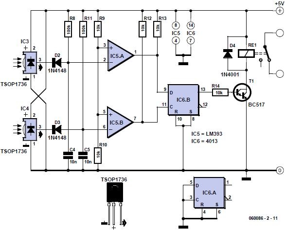
When used in a doorway, one transmitter is sufficient if the receivers are placed about 5 cm apart. With a wider passage, an installation with two separate IR-transmitters is a better solution. This circuit has a range of several meters, even if the sun shines directly on the receiver! We use the exact same IR-transmitter(s) as for the modulated light barrier. For the installation with two separate IR-transmitters it is sufficient to duplicate R6, T1, D1, C3 and R7 from the circuit of the modulated light barrier. Output OUT (pin 3) of IC2 can drive two of these IR-drivers without any difficulty. The receivers are slightly different than those of the modulated light barrier and the circuit is the same for both types of installation.

We again use the TSOP1736, which is sensitive to IR-light that is modulated at a frequency of 36 kHz. D2, R8 and C4 ensure that the received pulses from IC3 at the output of IC5a result in a ‘1’ when the beam is not interrupted. When the beam is interrupted this output will become a ‘0’ within about 1 ms. In the same way IC5b generates a ‘0’ when IC4 stops receiving IR-light. The 4013 CMOS-IC used here contains two D-flipflops, of which we use only one. The instant that light barrier 2 (IC4) is unblocked again, is used to clock the state of light barrier 1 (IC3) through to output Q1. This signal drives the relay via T2, which operates the light in the
room. The circuit therefore turns the light on or off the moment that light barrier 1 is uninterrupted.
Relate article: Modulated Light Barrier
Author: Heino Peters
(Elektor Electronics Magazine – 2006)
| * Download this article. |
Most homes today have at least a few infrared remote controls, whether they be for the television, the video recorder, the stereo, etc. Despite that fact, who among us has not cursed the light that remained lit after we just sat down in a comfortable chair to watch a good film? This project proposes to solve that problem thanks to its original approach. In fact, it is for a common on/off switch for infrared remote controls, but what differentiates it from the commercial products is the fact that it is capable of working with any remote control. Therefore, the first one you find allows you to turn off the light and enjoy your movie in the best possible conditions.

The infrared receiver part of our project is entrusted to an integrated receiver (Sony SBX 1620-52) which has the advantage of costing less than the components required to make the same function. After being inverted by T1, the pulses delivered by this receiver trigger IC2a, which is nothing other than a D flip-flop configured in monostable mode by feeding back its output Q on its reset input via R4 and C3. The pulse that is produced on the output Q of IC.2A makes IC.2B change state, which has the effect of turning on or turning off the LED contained in IC3. This circuit is an opto triac with zero-crossing detection which allows our setup to accomplish switching without noise. It actually triggers the triac T2 in the anode where the load to be controlled is found. The selected model allows us to switch up to 3 amperes but nothing should stop you from using a more powerful triac if this model turns out to be insufficient for your use.
In order to reduce its size and total cost, the circuit is powered directly from the mains using capacitor C5 which must be a class X or X2 model rated at 230 volts AC. This type of capacitor, called ‘selfhealing’, is the only type we should use today for power supplies that are connected to ground. ‘Traditional’ capacitors, rated at 400 volts, do not really have sufficient safety guarantees in this area. Considering the fact that the setup is connected directly to the mains, it must be mounted in a completely insulated housing. A power outlet model works very well and can easily be used to interspace between the grounded wall outlet
and that of the remote control device. Based on this principle, this setup reacts to any infrared signal and, as we said before, this makes it compatible with any remote control. On the other hand, it has a small disadvantage which is that sometimes it might react to the ‘normal’ utilization of one of these, which could be undesirable. To avoid that, we advise you to mask the infrared receiver window as much as possible so that it is necessary to point the remote control in its direction in order to activate it.
Author: Christian Tavernier
(Elektor Electronics Magazine – 2006)
| * Download this article. |
This small circuit is ideal for checking the basic operation of an infrared remote control unit.
The circuit is based on the brilliantly simple idea of connecting a piezo buzzer directly to an IR receiver IC.
This method is almost as simple as connecting a photodiode directly to the input of an oscilloscope, but has the advantage that no oscilloscope is needed: the compact unit is always ready to use and much easier to carry around than bulky test equipment.

Operation of the remote control is indicated by the buzzer making a chattering noise. The circuit is very sensitive and has a range of several metres. The TSOP1738 integrated IR receiver accepts, amplifies and demodulates the IR signal from the remote control, producing an output with a frequency of around 700 Hz. The piezo buzzer is connected to its output, rendering the signal audible.
All the other components are simply concerned with producing a stable 5 V power supply from the 9 V PP3-(6F22) type battery. Instead of the TSOP1738 similar devices from other manufacturers can be used, and of course carrier frequencies other than 38 kHz can be used. The circuit still works if there is a mismatch between the nominal carrier frequencies of the transmitter and receiver IC, but range is reduced. It is still, however, adequate for determining whether a remote control is producing an IR signal or not.
Author: Malte Fischer
(Elektor Electronics Magazine – 07-08/2006)
 | Download this article (direct link #060120-uk.pdf) |
