
When dealing with relays we distinguish between the pull-in voltage and the hold voltage. Depending on the type of device, the latter is from about 10 % to 50 % lower than the former. This means that once we have safely pulled in the relay armature we can drop the coil voltage to its hold value, thus reducing the power dissipated. The simple circuit shown here does just that: it consists of a parallel combination of an LED, an electrolytic capacitor and a resistor, together placed in series with the relay coil. As well as saving energy by reducing the operating current of the relay and increasing its operating life the circuit also has the advantage of providing a status indicator in the form of the LED.

The author has used this circuit with practically all types of relay, with various rated currents and voltages. The recommended component values are as follows:
• The electrolytic capacitor should have a value between 100 μF and 1000 μF with a working voltage of 6.3 V, depending on the rated current of the relay coil.
• The resistor value should be between 10 Ω and 1 kΩ so that in the active state a current of 20 mA flows through the LED.
• A standard green or yellow LED with a rated forward current of 20 mA should be used. When using relays with a very low coil current low-current LEDs may be substituted. Add a zener diode in series for higher coil voltages such as 24 V or 48 V.
Author: Klemens Viernickel
(Elektor Electronics Magazine – 2006)
 | * Download this article. |
The ZigBee standard defines data formats known as ‘profiles’. These ensure that products produced by different manufacturers are interoperable. One of the first data formats to be developed out was the Home Controls–Lighting (HCL) profile. This is designed for sending simple on/off messages, and its main purpose is designed to remove the need to run cables to wall-mounted light switches in buildings. However, that’s not to say that you can’t use it for switching anything else, for example, to add ZigBee remote control to your projects.
The Pixie Switcher from Flexipanel (www.flexipanel.com) is a commercially available HCL switching module with integral antenna and up to 8 switching control lines known as endpoints (EPs). When configured as an input, the endpoint voltage is monitored. If it changes state, a message is generated as required. ‘On’, ‘off’ and ‘toggle’ messages are supported by all devices using the HC-L profile. When configured as an output, the endpoint’s
digital output corresponds to the last message received from a switching input. Input endpoints to output endpoints correlation is managed by one-time setup procedures called ‘joining and binding’. When first powered up, a device will look for a ZigBee network to join. Security permitting, any router node can then allow the new node to become its neighbor in the network.
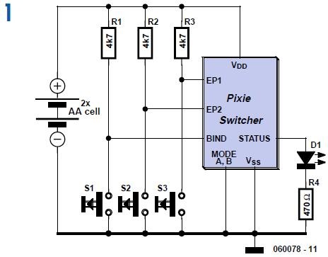
Once the new node has become a member of the network, its inputs and outputs must be ‘bound’ to corresponding outputs and inputs on other nodes in the network. This is achieved by pressing the ‘bind’ button on both devices at the same time. One input can control multiple outputs and vice versa. For example, it would be quite feasible for a bedside or hallway switch to turn off all the lights in the house. A typical application circuit is shown in the schematics, where one Pixie Switcher unit has been configured to have two inputs and the other to have two outputs. This configuration must be done prior to placing the modules in the circuit shown, using the RxD and TxD serial interface pins (not shown). Figure 1 shows the transmitter. The ModeA and ModeB pins are grounded, so the transmitter will operate in
sleep mode and only wake up when a button is pressed.
The modules can run at anything between 2.1 V and 3.3 V, so it can be connected directly to two AA batteries. The Bind input and Status LED are only used during joining and binding. When the pushbuttons connected to EP1 and EP2 are pressed, messages are transmitted to the receiver.

Figure 2 is the receiver. By setting ModeB high, it is configured as a router. This means it can allow battery powered sleeping devices (such as the transmitter) to join it as a neighbor. Routers, however, must be always-on and so are not really suited to battery powering. ModeA is also wired High, indicating that this router is in fact a coordinator. The difference between the two is that when a coordinator powers up, it starts a new network instead of looking for an existing one to join. Every ZigBee network has one coordinator. If further routers nodes were added to this network, they would have to have the ModeA pin low. EP1 and EP2 on the receiver are connected to relays via MOSFET driver transistors. The relay contacts can then be connected to any project circuit.
Author: Richard Hoptroff
(Elektor Electronics Magazine – 2006)
| * Download this article. |
In these times with viruses and other threats from the Internet it would be nice to have reassurance that the PC cannot be infected. That is why this circuit was designed. It makes it possible to install multiple hard disks inside the case of a PC, which are separated in such a way that viruses cannot move from one disk to another.
In this case there are three drives installed, one for use of the Internet via ADSL, one for working with email and one for other applications. If data from the Internet never arrives on the third disk, it is effectively protected against viruses. The solution outlined here has been in satisfactory use for a couple of years. There is an additional benefit: if there are ever any problems with the operation of the computer, then it is very easy to change to another hard disk to check if the problem manifests itself there as well. In this case, fault finding can be made much easier.

The circuit operates by only switching over the power supply voltages (5 V and 12 V) of the hard disks. The hard disk is out of service without a power supply. This works without a problem with S-ATA disks. With IDE disks this only works with modern drives. There may only be a combination of hard disks on the relevant port and no CD-ROM, DVD-drive, CDburner or something similar.
The selection of the desired hard disk is done with a rotary switch. This has to be set to the correct position before the computer is switched on. When the power supply is turned on, one of three relays is driven via diode D1, D2 or D3. The relays are provided with a hold circuit via a second diode (D4, D5 and D6). In this way the selected relay remains energized as long as the power supply voltage is present. After switching on, electrolytic capacitor C1 is charged via R1, so that the common contact of the rotary switch is quickly at 0 V. This prevents an accidental change of hard disk while the computer is in operation.
The ADSL modem is powered from the PC. This power supply voltage is only present if hard disk number 2 is selected. This prevents the use of the Internet if one of the other disks is selected.
Author: Uwe Kardel
(Elektor Electronics Magazine – 2006)
| * Download this article. |
Many power woodworking tools such as saws and sanders have a provision for connecting a vacuum cleaner hose to suck up the dust and debris produced by their operation. The problem is of course that the vacuum cleaner must be switched on when the tool is switched on and as the operator’s attention must be directed towards the work in hand especially when a blade with large teeth is spinning only inches from his fingers, there is often little incentive to look away to locate the vacuum cleaner switch. This unit was designed to fulfill this function by automatically switching on the vacuum cleaner when the power tool is switched on.
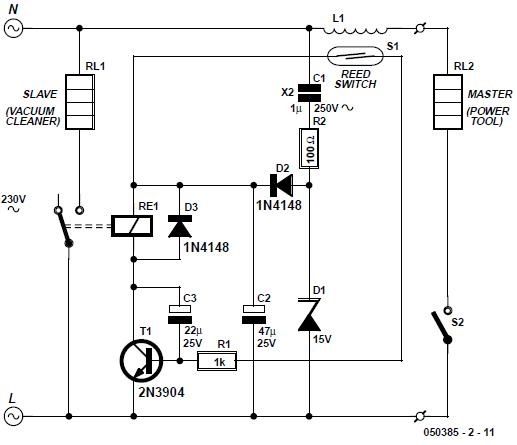
In this circuit, current flow is sensed using a reed relay which is not only cheap but provides a positive indication that current is flowing and dissipates very little power. Reed switches are often used in burglar alarms where they sense the magnetic field from a small magnet but
it is also possible to produce a magnetic field by winding a coil around the reed switch and passing a current through this. The circuit diagram shows a simple mains slave switch based on this idea. The coil may be wound directly onto the reed switch using insulated single core hook-up wire or enamelled copper wire of sufficient gauge to carry the current drawn by the power tool (or master appliance). In practice this should be as thick as possible to cater for any power appliance while still enabling a sufficient number of turns to be accommodated to produce the required magnetic field which will depend on the reed switch and is therefore best determined by experiment. As a guide, a one-inch reed switch with 40 turns reliably switched on with the current flowing through a 150-watt lamp (approx. 625 mA) but larger reeds may require more turns. If the master appliance draws less current (which is unlikely with power tools) more turns will be required. The reed switch is used to switch on transistor
T1 which in turn switches the relay RE1 and powers the slave appliance.
Author: Bart Trepak
(Elektor Electronics Magazine – 2006)
| * Download this article. |
How often does it happen that you close down Windows and then forget to turn off the computer? This circuit does that automatically. After Windows is shut down there is a ‘click’ a second later and the PC is disconnected from the mains. Up to now there were no mains switches available with a magnetic coil to turn off the power supply voltage, but now one is available from Conrad Electronics , with the article number 70061 for a price of 12.95 Euro (approx. £ 9.00). Surprisingly enough, this switch fits in some older computer cases. If the circuit doesn’t fit then it will have to be housed in a separate enclosure. That is why a supply voltage of 5 V was selected. This voltage can be obtained from a USB port when the circuit has to be on the outside of the PC case.

A PCB design is available for the electronics part, but not for the high voltage part. It is best to solder the mains wires straight onto the switch and to insulate them with heat shrink sleeving. C8 is charged via D1. This is how the power supply voltage for IC1 is obtained. A square wave oscillator is built around IC1a, R1 and C9, which drives inverters IC1c to f. The frequency is about 50 kHz. The four inverters in parallel power the voltage multiplier, which has a multiplication of 3, and is built from C1 to C3 and D2 to D5. This is used to charge C5 to C7 to a voltage of about 9 V. The generated voltage is clearly lower than the theoretical 3x4.8=14.4 V, because some voltage is lost across the PN-junctions of the diodes. C5 to C7 form the buffer that powers the coil of the switch when switching off. The capacitors charge up in about two seconds after switching on. The circuit is now ready for use. When Windows is closed down, the 5-V power supply voltage disappears. C4 is discharged via R2 and this results in a ‘0’ at the input of inverter IC1b. The output then becomes a ‘1’, which causes T1 to turn on. A voltage is now applied to the coil in the mains switch and the power supply of the PC is turned off. T1 is a type BSS295 because the resistance of the coil is only 24 Ω.
When the PC is switched on, the circuit draws a peak current of about 200 mA, after which the current consumption drops to about 300 μA. The current when switching on could be higher because this is strongly dependent on the characteristics of the 5-V power supply and the supply rails in the PC.
There isn’t much to say about the construction of the circuit itself. The only things to take care with are the mains wires to the switch. The mains voltage may not appear at the connections to the coil. That is why there has to be a distance of at least 6 mm between the conductors that are connected to the mains and the conductors that are connected to the low-voltage part of the circuit. Also refer to the Electrical Safety page published from time to time In this magazine.
Author: Uwe Kardel
(Elektor Electronics Magazine – 2006)
| * Download this article. |
Come to think about it, it’s a bit strange that range hoods in our kitchens don’t switch on and off automatically. After all, a simple temperature sensor under the hood can detect whether a burner is on. The circuit described here goes a step further and compares the temperature under the hood with the temperature just outside the hood. At a certain (adjustable) temperature difference, the hood will be switched on, possibly along with the lamp under the hood. After the burners are shut off, the hood fan and lamp will switch off again by themselves. The advantage of using two sensors is that the hood will have the same switching characteristics in the summer as in the winter.

When building the circuit, it’s important to ensure that IC1 is located beneath the hood in the middle and IC2 is located next to the hood or above it. If the temperature under the hood is higher than the temperature outside it, the open-collector output of IC3 will be pulled up to the supply voltage by R6. The combination of IC3 and R7–R11 forms a Schmitt trigger, which we need because the output of IC3a does not change immediately from 0 V to the supply voltage (or vice versa) in the transition region. The output of the IC3b will thus be at the supply voltage, which will switch on T1 via R11. That causes the relay to engage and switch on the fan and lamp of the range hood. R2 can be used to adjust the output voltage of IC1 over a range of approximately 0.1 V, which corresponds to around 10 °C. It’s a good idea to use a supply voltage that matches the operating voltage of the relay. It’s also convenient to fit the relay in a small box with an electrical outlet and plug so it can be easily and safely inserted between the plug and outlet of the range hood.
The circuit works best with a gas cooker, because the heat rises immediately after a burner is lit. With a ceramic or inductive cooking top, it takes a bit longer for the relay to be actuated.
Author: Heino Peters
(Elektor Electronics Magazine – 7-8/2006)
 | * Download this article. |
Mechanical contacts have the disadvantage that they wear out. That is why it is practical to use an electronic ‘touch switch’ in some situations. With such a touch switch the resistance of the human skin is used for the switching action.
The schematic shows the design of a circuit that senses the resistance of the skin and converts it into a useful switching signal. The touch switch contacts can be made from two small metal plates, rivets, nails, etcetera, which are placed close together on a non-conducting surface. In this circuit a comparator of the type LM393 has been used.

In the idle state there is, via R1, a voltage equal to the power supply voltage on the non-inverting input of IC1a. Because the inverting input of IC1a is set with R2 and D3 to D5 at the supply voltage minus 1.8 V, the open-collector output of IC1.a is, via R3, equal to the power supply voltage. This voltage is inverted by IC1.b. The voltage at the non-inverting input of IC1.b amounts to half the power supply voltage (through voltage divider R4 and R5) and is lower than the voltage on the inverting input. The output of IC1.b is therefore a ‘0’. If the two touch contacts are bridged with a finger, the voltage at the non-inverting input will become low enough to cause the comparator to toggle state. The moistness of the skin results in a resistance of 1 to 10 MΩ.
If this circuit is used in the vicinity of equipment that’s connected to the mains, then it can be sufficient to touch only the upper contact to operate the switch, provided that the circuit has been earthed. The body then acts as an antenna which receives the 50 Hz (or 60 Hz) from the
mains. This is enough to toggle IC1.a at the same 50 Hz. C1/R3 prevent this 50 Hz from reaching the input of IC1b and provide a useable ‘pulse’ of about 10 s at the output of IC1.b.
Note that a fly walking across the touch switch conducts enough to generate a switching signal. So do not operate important things with this circuit (such as the heating system or the garage door). Do not make the wires between the touch contacts and the circuit too long to prevent picking up interference. The power supply voltage for the circuit is not very critical. Any regulated DC voltage in the range from 6 to 20 V can be used.
Author: Heino Peters
(Elektor Electronics Magazine – 07-08/2006)
| | Download this article (direct link #060084.pdf) |
This circuit switches a printer’s USB connection from a PC to a laptop. What was needed was a method of allowing a laptop to use the printer occasionally while at all other times the printer would be connected to the PC. Instead of unplugging the printer from the PC and then into the laptop, the circuit switches the USB connection automatically. K1 and K2 are standard type-B USB sockets, while K3 is a USB type-A socket. The USB lead from the laptop plugs into K2 while the PC’s USB lead plugs into K1. A USB cable from K3 connects the printer to this circuit. The cable from the PC is always plugged in while the cable from the laptop is only connected whenever this device needs to print.

In normal operation the laptop is not connected to K2, so the USB signal to the printer comes from the PC via K1, the normally closed contacts of relay Re1, through to K3 and from there to the printer. Whenever the laptop is connected up, the presence of the 5- volt power signal on its USB port causes Re1 to switch over to the printer’s connection to K2 and the laptop. Unplugging the laptop returns control of the printer back to there PC.
The circuit was tested on a USB 1.1 compliant printer and a PC and laptop that had USB-2.0 highspeed ports. The PCB traces for D+ and D– should be kept as short as possible and ideally should be the same length. The relay should be a low-power type (5 V at <100 mA coil current) with two changeover (c/o) contacts.
Switch S1 is only required in situations where the two computers you want to select between are permanently present and connected up to the circuit. The switch then selects the computer having access to the printer.
Author: Liam Maskey
(Elektor Electronics Magazine – 07/2006)
| | Download this article (direct link #060103-uk.pdf) |
Author: Tom Henskens
This circuit can be used to turn the pump on and off when a solar collector is used to heat a swimming pool, for example. This way the water in the collector has a chance to warm up significantly before it is pumped to the swimming pool. A bonus is that the pump doesn’t need to be on continuously.

The basis of operation is as follows. When the temperature of the water in the solar collector is at least 10 °C higher than that of the swimming pool, the pump starts up. The warm water will then be pumped to the swimming pool and the temperature difference will drop rapidly. This is because fresh, cool water from the swimming pool enters the collector.
Once the difference is less than 3 °C the pump is turned off again.
R10/R1 and R9/R2 each make up a potential divider. The output voltage will be about half the supply voltage at a temperature around 25 °C.
C7 and C8 suppress any possible interference. The NTCs (R9 and R10) are usually connected via several meters of cable, which can easily pick up interference. Both potential dividers are followed by a buffer stage (IC1a/IC1b). IC1c and R3, R4, R5 and R6 make up a differential amplifier (with unit gain), which measures the temperature difference (i.e. voltage difference).
When both temperatures are equal the output is 0 V. When the temperature of the solar collector rises, the differential amplifier outputs a positive voltage. This signal is used to trigger a comparator, which is built round an LM393 (IC2a). R7 and P1 are used to set the reference voltage at which the comparator changes state. R8 and P2 provide an adjustable hysteresis. R11 has been added to the output of IC2a because the opamp has an open collector output.
A power switch for the pump is created by R12, T1 and Re1. D1 protects T1 against voltage spikes from the relay coil when it is turned off.
A visual indication of the state of the controller is provided by IC4 (UAA170), a LED spot display driver with 16 LEDs. The reference voltage for the comparator is buffered by IC1d and fed to input VRMAX of the UAA170. R20/D21 and R23/D22 limit the input voltages of IC4 to 5.1 V, since the maximum permissible input voltage to the UAA170 is 6 V.
When there is no temperature difference, LED D20 turns on. As the temperature difference
increases the next LED turns on. The full scale of the LED bar is equal to the reference voltage of the comparator. This means that when the last LED (D5) of the UAA170 turns on, the comparator switches state. This is also indicated by D2.
The power supply has been kept fairly simple and is built around a LM7812 regulator. The circuit is protected against a reverse polarity at the input by D3. You have to make sure that the input to the regulator is at least 15 V, otherwise it won’t function properly.
There are a few points you should note regarding the mounting of the NTCs. NTC R9 should be placed near the output of the solar collector. You should choose a point that always contains water, even when some of the water flows back a little. NTC R10 should be mounted inside the filter compartment (where it exists), which continually pumps the swimming pool water. This will give a good indication of the temperature of the water.
The way the circuit has to be set up depends how it has been installed and is very much an experimental process. To start with, set hysteresis potentiometer (P2) halfway. Then set the reference voltage to about 1.5-2 V with P1. On a sunny day you can measure the voltage difference to get an idea as to which reference voltage needs to be adjusted.
The hysteresis setting determines how long the pump stays on for, which is until the minimum temperature difference has been reached.
(Elektor Electronics Magazine – 07/2006)
| | Download this article (direct link #050217-uk.pdf) |
Author: Paul Goossens

A device with such functionality is eminently suitable for building yourself. The schematic shows that it can be easily realised with a few standard components.
The servo signal, which consists of pulses from 1 to 2 ms duration, depending on the desired position, enters the circuit via pin 1 of connector K1. Two buffers from IC2 provide the necessary buffering after which the signal is differentiated by C2. This has the effect that at each rising edge a negative start signal is presented to pin 2 of IC1. D1 and R4 make sure that at the falling edge the voltage at pin 2 of IC2 does not become too high. IC1 (TLC555) is an old faithful in a CMOS version. A standard version (such as the NE555) works just as well, but this
IC draws an unnecessarily high current, while we strive to keep the current consumption as low as possible in the model.
The aforementioned 555 is configured as a one-shot. The pulse-duration depends on the combination of R2/C1. Lowering the voltage on pin 5 also affects the time. This results in reducing the length of the pulse. In this circuit the pulse at the output of IC will last just over 1.5 ms when T1 does not conduct. When T1 does conduct, the duration will be a little shorter than 1.5 ms. We will explain the purpose of this a little later on.
Via IC2.C, the fixed-length pulse is, presented to the clock input of a D-flip-flop. As a consequence, the flip-flip will remember the state of the input (servo signal). The result is that when the servopulse is longer than the pulse form the 555, output Q will be high, otherwise the output will be low.

It is possible, in practice, that the servo signal is nearly the same length as the output from the 555. A small amount of variation in the servo signal could therefore easily cause the output to ‘chatter’, that is, the output could be high at one time and low the next. To prevent this chatter there is feedback in the form of R1, R3 and T1. This circuit makes sure that when the flip-flip has decided that the servo-pulse is longer than the 555’s pulse (and signals this by making output Q high), the pulse duration from the 555 is made a little shorter. The length of the servo-signal will now have to be reduced by a reasonable amount before the servo-pulse becomes shorter than the 555’s pulse. The moment this happens, T1 will stop conducting and the mono-stable time will become a little longer. The servo-pulse will now have to be longer
by a reasonable amount before the flip-flip changes back again. This principle is called hysteresis.
Jumper JP1 lets you choose between thenormal or inverted output signals. Buffers IC2.D through to IC2.F together with R5 drive output transistor T2, which in turn drives the output. Note that the load may draw a maximum current of 100 mA. Diode D2 has been added so that inductive loads can be switched as well (for example, electrically operated pneumatic valves).
COMPONENTS LIST
| Resistors: | Capacitors: | Semiconductors: | Miscellaneous: |
(Elektor Electronics Magazine – 07/2006)
| | Download this article (#044030-uk.pdf) |
