
Most homes today have at least a few infrared remote controls, whether they be for the television, the video recorder, the stereo, etc. Despite that fact, who among us has not cursed the light that remained lit after we just sat down in a comfortable chair to watch a good film? This project proposes to solve that problem thanks to its original approach. In fact, it is for a common on/off switch for infrared remote controls, but what differentiates it from the commercial products is the fact that it is capable of working with any remote control. Therefore, the first one you find allows you to turn off the light and enjoy your movie in the best possible conditions.

The infrared receiver part of our project is entrusted to an integrated receiver (Sony SBX 1620-52) which has the advantage of costing less than the components required to make the same function. After being inverted by T1, the pulses delivered by this receiver trigger IC2a, which is nothing other than a D flip-flop configured in monostable mode by feeding back its output Q on its reset input via R4 and C3. The pulse that is produced on the output Q of IC.2A makes IC.2B change state, which has the effect of turning on or turning off the LED contained in IC3. This circuit is an opto triac with zero-crossing detection which allows our setup to accomplish switching without noise. It actually triggers the triac T2 in the anode where the load to be controlled is found. The selected model allows us to switch up to 3 amperes but nothing should stop you from using a more powerful triac if this model turns out to be insufficient for your use.
In order to reduce its size and total cost, the circuit is powered directly from the mains using capacitor C5 which must be a class X or X2 model rated at 230 volts AC. This type of capacitor, called ‘selfhealing’, is the only type we should use today for power supplies that are connected to ground. ‘Traditional’ capacitors, rated at 400 volts, do not really have sufficient safety guarantees in this area. Considering the fact that the setup is connected directly to the mains, it must be mounted in a completely insulated housing. A power outlet model works very well and can easily be used to interspace between the grounded wall outlet
and that of the remote control device. Based on this principle, this setup reacts to any infrared signal and, as we said before, this makes it compatible with any remote control. On the other hand, it has a small disadvantage which is that sometimes it might react to the ‘normal’ utilization of one of these, which could be undesirable. To avoid that, we advise you to mask the infrared receiver window as much as possible so that it is necessary to point the remote control in its direction in order to activate it.
Author: Christian Tavernier
(Elektor Electronics Magazine – 2006)
 | * Download this article. |
The ZigBee standard defines data formats known as ‘profiles’. These ensure that products produced by different manufacturers are interoperable. One of the first data formats to be developed out was the Home Controls–Lighting (HCL) profile. This is designed for sending simple on/off messages, and its main purpose is designed to remove the need to run cables to wall-mounted light switches in buildings. However, that’s not to say that you can’t use it for switching anything else, for example, to add ZigBee remote control to your projects.
The Pixie Switcher from Flexipanel (www.flexipanel.com) is a commercially available HCL switching module with integral antenna and up to 8 switching control lines known as endpoints (EPs). When configured as an input, the endpoint voltage is monitored. If it changes state, a message is generated as required. ‘On’, ‘off’ and ‘toggle’ messages are supported by all devices using the HC-L profile. When configured as an output, the endpoint’s
digital output corresponds to the last message received from a switching input. Input endpoints to output endpoints correlation is managed by one-time setup procedures called ‘joining and binding’. When first powered up, a device will look for a ZigBee network to join. Security permitting, any router node can then allow the new node to become its neighbor in the network.
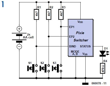
Once the new node has become a member of the network, its inputs and outputs must be ‘bound’ to corresponding outputs and inputs on other nodes in the network. This is achieved by pressing the ‘bind’ button on both devices at the same time. One input can control multiple outputs and vice versa. For example, it would be quite feasible for a bedside or hallway switch to turn off all the lights in the house. A typical application circuit is shown in the schematics, where one Pixie Switcher unit has been configured to have two inputs and the other to have two outputs. This configuration must be done prior to placing the modules in the circuit shown, using the RxD and TxD serial interface pins (not shown). Figure 1 shows the transmitter. The ModeA and ModeB pins are grounded, so the transmitter will operate in
sleep mode and only wake up when a button is pressed.
The modules can run at anything between 2.1 V and 3.3 V, so it can be connected directly to two AA batteries. The Bind input and Status LED are only used during joining and binding. When the pushbuttons connected to EP1 and EP2 are pressed, messages are transmitted to the receiver.

Figure 2 is the receiver. By setting ModeB high, it is configured as a router. This means it can allow battery powered sleeping devices (such as the transmitter) to join it as a neighbor. Routers, however, must be always-on and so are not really suited to battery powering. ModeA is also wired High, indicating that this router is in fact a coordinator. The difference between the two is that when a coordinator powers up, it starts a new network instead of looking for an existing one to join. Every ZigBee network has one coordinator. If further routers nodes were added to this network, they would have to have the ModeA pin low. EP1 and EP2 on the receiver are connected to relays via MOSFET driver transistors. The relay contacts can then be connected to any project circuit.
Author: Richard Hoptroff
(Elektor Electronics Magazine – 2006)
| * Download this article. |
This small circuit is ideal for checking the basic operation of an infrared remote control unit.
The circuit is based on the brilliantly simple idea of connecting a piezo buzzer directly to an IR receiver IC.
This method is almost as simple as connecting a photodiode directly to the input of an oscilloscope, but has the advantage that no oscilloscope is needed: the compact unit is always ready to use and much easier to carry around than bulky test equipment.

Operation of the remote control is indicated by the buzzer making a chattering noise. The circuit is very sensitive and has a range of several metres. The TSOP1738 integrated IR receiver accepts, amplifies and demodulates the IR signal from the remote control, producing an output with a frequency of around 700 Hz. The piezo buzzer is connected to its output, rendering the signal audible.
All the other components are simply concerned with producing a stable 5 V power supply from the 9 V PP3-(6F22) type battery. Instead of the TSOP1738 similar devices from other manufacturers can be used, and of course carrier frequencies other than 38 kHz can be used. The circuit still works if there is a mismatch between the nominal carrier frequencies of the transmitter and receiver IC, but range is reduced. It is still, however, adequate for determining whether a remote control is producing an IR signal or not.
Author: Malte Fischer
(Elektor Electronics Magazine – 07-08/2006)
 | Download this article (direct link #060120-uk.pdf) |
Author: Carlos Ferreira

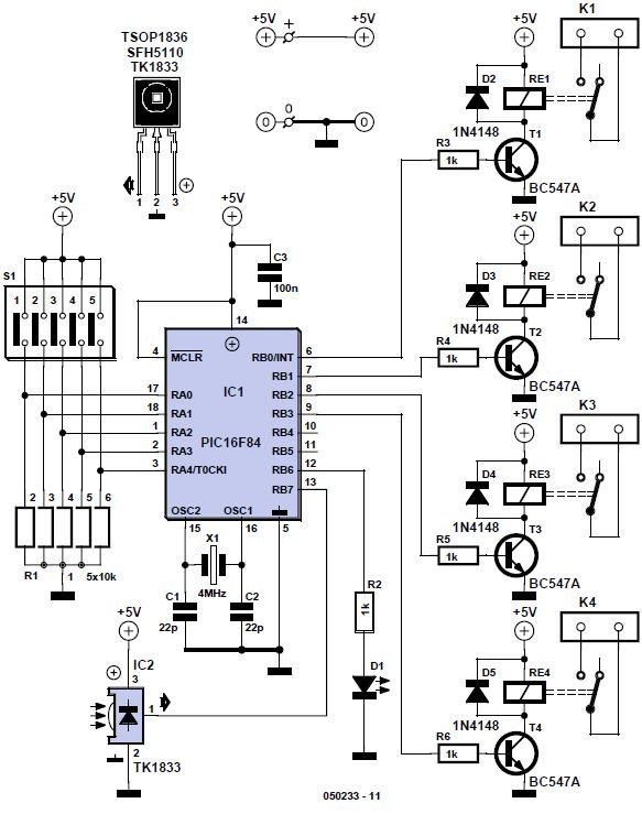
The circuit designed for maximum indolence in front of the telly is built around the PIC16F84. The ‘F84 was chosen mainly because of its internal EEPROM, which is necessary to store the user-programmable infrared codes. To control such devices as mentioned above, four relays are used, working together with lamp switches in a two way configuration.
Looking at the circuit, the DIP switch block and the associated resistor array connected to microcontroller port A are used to program the IR codes and to select the operation mode for all the outputs (described further on). The IR sensor is connected to port line RB7 on the PIC. The lower nibble (set of 4 bits) of port B is used to control the output relays via 1-k resistors and BC547 transistors. It is also used to control multifunction indicator LED D1 on port line RB6.
Components C1, C2 and X1 generate the microcontroller clock signal while C3 helps to keep the supply voltage as clean as possible.
The circuit should be powered by a 5-V regulated supply capable of providing enough current for the four relay coils (approximately 140 mA per relay) plus a few mA for microcontroller, IR sensor and LED.
The circuit is designed to respond to infrared commands coded to the Philips RC5 protocol. The protocol consists in a frame of 14 bits. The first two bits, always at ‘1’, are used to start the frame. The third bit is the flip bit, this bit indicates when a key is pressed repeatedly. The next five bits are used to identify de system which the message is sent. The last six bits represent the sent command. Note that in RC5 speak a logic ‘1’ is a transition from 0 V to Vcc, and logic ‘0’ is a transition from Vcc to 0 V, where the period of one bit is 1.7778 ms. Many
articles on RC5 have appeared in this magazine.
The software developed for the project is stored in the PIC microcontroller. It allows four different RC5 codes to be saved and used to control the four outputs. For example, your TV remote may be able to control five systems: TV (default), VCR, DVD, AMP, SAT. If, for example, you do not have VCR then the relevant IR codes are available for Easy Home Control. If your remote control is not compatible with RC5 codes, you can buy a cheap universal remote control to do the job. To avoid the relays changing state owing to a power cut in your home, the state of the relays is saved in the microcontroller EEPROM and retrieved every time the PIC re-initialises.

The actuation of electric curtains differs from lamps as it’s necessary to send a short pulse to the relays. To make the home control more versatile it is possible to control all relays (configurable by the DIP switches) in one of two modes:
• toggle between ON and OFF positions with memory for lamps;
• output pulse for other devices like electric windows-curtains.
If you’re a keen energy saver, it is also possible to program an IR code to turn off all the relays (and save 5 V·140 mA = 0.7 watts per relay).
The Easy Home Remote Control is configured as follows.
1. Switch the circuit on with all DIP switches set to OFF.
2. Flip ON switch #5 (switch connected to RA4/TOCK1) to enable programming mode. Using Table 1, set the other switches as required to save desired IR codes in EEPROM.
3. Flip OFF switch #5 to select working mode. Using Table 2, configure the other switches to select the desired relay mode.


File number 050233-11.zip may be found by clicking on Magazine → 2006 → July/August. The PIC is also available ready-programmed from the Publishers as order code 050233-41.
COMPONENTS LIST
| Resistors Capacitors | Semiconductors | Miscellaneous |
(Elektor Electronics Magazine – 07/2006)
| | Download this article (#050233-uk.pdf)  050233-11.zip >> or direct link. |
Author: Paul Goossens

A device with such functionality is eminently suitable for building yourself. The schematic shows that it can be easily realised with a few standard components.
The servo signal, which consists of pulses from 1 to 2 ms duration, depending on the desired position, enters the circuit via pin 1 of connector K1. Two buffers from IC2 provide the necessary buffering after which the signal is differentiated by C2. This has the effect that at each rising edge a negative start signal is presented to pin 2 of IC1. D1 and R4 make sure that at the falling edge the voltage at pin 2 of IC2 does not become too high. IC1 (TLC555) is an old faithful in a CMOS version. A standard version (such as the NE555) works just as well, but this
IC draws an unnecessarily high current, while we strive to keep the current consumption as low as possible in the model.
The aforementioned 555 is configured as a one-shot. The pulse-duration depends on the combination of R2/C1. Lowering the voltage on pin 5 also affects the time. This results in reducing the length of the pulse. In this circuit the pulse at the output of IC will last just over 1.5 ms when T1 does not conduct. When T1 does conduct, the duration will be a little shorter than 1.5 ms. We will explain the purpose of this a little later on.
Via IC2.C, the fixed-length pulse is, presented to the clock input of a D-flip-flop. As a consequence, the flip-flip will remember the state of the input (servo signal). The result is that when the servopulse is longer than the pulse form the 555, output Q will be high, otherwise the output will be low.

It is possible, in practice, that the servo signal is nearly the same length as the output from the 555. A small amount of variation in the servo signal could therefore easily cause the output to ‘chatter’, that is, the output could be high at one time and low the next. To prevent this chatter there is feedback in the form of R1, R3 and T1. This circuit makes sure that when the flip-flip has decided that the servo-pulse is longer than the 555’s pulse (and signals this by making output Q high), the pulse duration from the 555 is made a little shorter. The length of the servo-signal will now have to be reduced by a reasonable amount before the servo-pulse becomes shorter than the 555’s pulse. The moment this happens, T1 will stop conducting and the mono-stable time will become a little longer. The servo-pulse will now have to be longer
by a reasonable amount before the flip-flip changes back again. This principle is called hysteresis.
Jumper JP1 lets you choose between thenormal or inverted output signals. Buffers IC2.D through to IC2.F together with R5 drive output transistor T2, which in turn drives the output. Note that the load may draw a maximum current of 100 mA. Diode D2 has been added so that inductive loads can be switched as well (for example, electrically operated pneumatic valves).
COMPONENTS LIST
| Resistors: | Capacitors: | Semiconductors: | Miscellaneous: |
(Elektor Electronics Magazine – 07/2006)
| | Download this article (#044030-uk.pdf) |
Switch & Control using DTMF signalling
Author: Heikki Kalliola
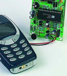
The overall complexity of the circuit is greatly reduced by the use of a PIC microcontroller. The addition of a speech synthesizer chip allows the control unit to return spoken information to the user on the calling phone.
The system
The schematic of the Remote Control by Mobile Phone is given in Figure 1. The connector for the headset is plugged into the mobile phone and the wires to the earphone pieces are connected to the input of a DTMF decoder IC type 8870 (IC1). The received signals are amplified by T1 and then applied to pin RB2 of the central microcontroller, a PIC16F84 (IC2). DTMF stands for dual-tone multi-frequency, a tone coding/decoding system that’s been in use on wired telephone sets for almost 30 years now. Each key on the DTMF keypad is linked to a combination of two (nonharmonically related) tones in the audible range. At the receiving side, the tone pairs are decoded into the matching number (0-9, #, *).
For our application, the mobile phone is set to auto-answer mode. In operation, the PIC micro will continuously monitor the level at RB7 (pin 13). A ring signal will wake up the PIC from its sleep state and cause it to activate the speech chip (IC3) which supplies a ‘spoken’ message to the mobile phone via the microphone connector of the headset. At the calling end, the user hears the welcome message and is prompted to enter the system password (MSG1). The level of the audio signal may be adjusted on preset P2. The selection of spoken text stored in the speech chip is determined by the logic state of control lines A6, A7 and A8.
Figure 1. The circuit contains just three ICs: a DTMF decoder, a PIC micro looking after the internal control functions, and a speech chip.

Next, the program running inside the PIC will wait for certain DTMF tones entered by the user on his/her phone (mobile or landline). The received DTMF signals are decoded into the matching numbers by IC1, which supply binary output information on outputs Q1-Q4, with output STD (pin 15) flagging reception of a valid code to the PIC.
Having received a valid 4-digit password (which is being compared to the one stored in the PIC’s memory), the system will request a function code (MSG2). Depending on the information received in response to MSG2, the micro will pull its RB5 control line logic Low or High. This signal enables a relay to switch a suitably wired up electrical appliance in your home to be switched on or off (for example, a coffee machine or the central heating). The relay may be a solid-state device (which allows direct control from RB5), or a traditional solenoid-based switcher that’s controlled via a transistor buffer. The action executed at the receiving side is confirmed with a spoken message (MSG4 or MSG5). The speech chip contains yet other text messages (MSG3, MSG6 and MSG7) for the processing of situations ‘out of the ordinary’.
The speech chip
The spoken messages are supplied by a type ISD25120 speech synthesiser which has storage capacity for about two minutes worth of speech. Different memory areas inside the ISD25120 may be selected using address lines A0-A9. Here, the memory has been divided into eight chunks of about 15 seconds that can be individually addressed over A6, A7 and A8. This allows the PIC to select any individual spoken messages and have it played back by pulling the CE control input Low. The spoken messages may be recorded and checked using a microphone and a small loudspeaker connected to IC3. Switches S4, S5 and S6 select the relevant memory area. The relevant message is then recorded on the chip via MIC1 while S2 is pressed. The pushbutton should be released at the end of your message, which can be listened to by briefly pressing S1 (this requires switch S7 to be closed). If you are not satisfied with the result, the text may be re-recorded. During recording ad playing back the messages (for checking) the PIC has to be removed from its socket, else IC3’s address lines cannot be set manually. The inset ‘Messages’ gives examples of texts you could use for the voice feedback, including the associated address settings.
Password changing
In an application like this, where equipment is controlled from a remote location, it is essential to prevent unauthorised access. In any case, password protection is required. You, the user, may pick your own 4-digit password using the number keys on your mobile phone’s keypad. For this to work you have to open switch S3 (which is closed during normal use). In that case, the four numbers entered on the calling phone after the welcome message has finished will be accepted as the new password, and subsequently stored in the PIC’s RAM memory. If mains outages are common in your home, we recommend powering the circuit from a battery system with mains charging, else the password will be lost.

Figure 2. Copper track layout and component mounting plan of the PCB designed for the remote control. Be sure to use sockets for the ICs, as the PIC has to be removed during recording of the spoken messages.
COMPONENTS LIST
| Resistors: | Semiconductors: |
| Capacitors: | Miscellaneous: |
Construction
The above article text having largely described the operation and practical use of the circuit, you should know the function of all switches and other controls and use this information to fit the relevant parts on the case in such a way that the unit is easy to operate in practice.
The source code of the PIC control program written by the author is available as a free download from our website, as well as on floppy disk (order code 040415-11). Those without access to a suitable PIC programmer may also buy the PIC micro ready-programmed as
order code 040415-41.
The PCB artwork is shown at true size in Figure 2. With all components fitted (insert the ICs in sockets) the controls may be connected up via short lengths of stiff wire: S1, S2, S3, S4, S5 and S6, the electret microphone capsule and (if required) the loudspeaker (together with S7). The latter parts are mainly needed to check the spoken messages, switch S7 allowing the loudspeaker to be switched off during normal use. Next, the mobile phone link may be hooked up on connector K1. The output relay for the electrical appliance you wish to control (literally from anywhere in the civilised world!) is connected to the terminals beside S3 on the board. The circuit is happy with a 6-15 VDC supply voltage from a mains adaptor capable of supplying 100 mA or so. There is only one adjustment in the circuit: preset P1 determines the input sensitivity of the DTMF IC. The setting is not critical however and the circuit will usually work with the wiper at mid travel.
| What mobile phone? 1. You will require a mobile with a headset. The headset may be faulty or incomplete — basically we only need the connector. 2. Some mobiles will not detect the headset when no microphone is connected. 3. The mobile has to support ‘auto-answer mode’, that is, it has to be able to answer an incoming call on the first ring signal. Some mobiles will not show this option until a headset is actually connected. 4. The ring signal has to be audible in the headset, too, as it its function is to ‘wake’ the PIC via T1/RB7. The first pulse edge on the PIC’s port pin indicates that DTMF odes are imminent and also causes IC3 to play back the welcome message. If the ring signal is not sent to the headset the circuit may also be activated by saying something into the calling phone. |


(Elektor Electronics Magazine - 11/2005)
| | Download this article #e05b040.pdf >>or SkyDrive link #040415-11.zip >> or SkyDrive link |
Enhancing remote controlled lighting

Remote controlled light switches are becoming more and more common. DIY stores have inexpensive sets consisting of several light switches and a remote control unit. It’s then easy to control everything from your armchair. But how can you control the lighting when you’re away, as a deterrent to burglars? With the help of this little circuit that is no longer a problem.
With modern technology it sometimes happens that you replace one problem with another. Or as Johan Cruyff, the greatest Dutch soccer player of all times eloquently said: “every advantage have its disadvantage”. The circuit described here has been designed to overcome a shortcoming of wireless remote controls for domestic lighting. The problem is this: when people go way on holiday they often connect ordinary lights directly to time switches to turn the lights on and off at certain times. This gives the impression that the house is still occupied, but it can also come in useful when visitors, who stay till the small hours of the night, need a little hint that it’s time to go! But when these lights are controlled wirelessly it is unfortunately no longer possible to switch them on and off with a time switch. The light switches work with a signal that is transmitted via radio or infrared by the remote control handset. And herein lies the problem: who controls the remote control in your absence? You can’t expect your neighbours to do this for you, even if you get on very well with them. Fortunately, with a little inventiveness and some electronics we can get round this problem.
Figure 1. The circuit consists entirely of discrete components. (click to enlarge)

Electronic control of switches
With this circuit we can add electronic switches in parallel with the buttons in the remote control. Of course your remote control has to be suitable for this modification. This will be covered in detail later, in the section “Modifying the remote control”. To keep things simple, we have catered for a maximum of four lights. The remote control unit we bought had one on-switch and one off-switch for each light. For four lights we therefore need to control eight switches externally. The receivers are turned on by closing the four ‘on’ contacts equentially, with a short pause in between. They are turned off again by closing the four ‘off’ contacts sequentially, with a short pause in between.
The circuit
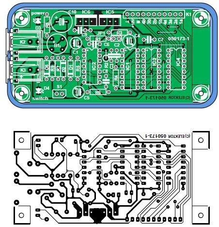
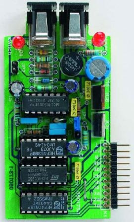
Figure 2. The copper track and component layout of the PCB designed for the project.
As you can see from Figure 1, this time we found a solution without the use of a microcontroller. It does mean that a fair number of components are used in the circuit, but they are all without exception easily obtainable and inexpensive. In the original design we wanted to control this circuit via an ordinary switch or the switch inside a time switch.
This means that we would first have to open up the time switch to disconnect the internal microswitch from the mains. Apart from the fact that this involves a lot of tinkering, it is not always possible. We would also have to make sure that all safety regulations were adhered to!
It is much simpler to control the circuit with a voltage and use a separate mains adapter; you probably have one left over from an old mobile phone or other device (5 V to 9 V DC). This also keeps everything safe, since the adapter simply plugs into the time switch! You then set the time switch to the required times when the lights should go on and off, and the mains adapter provides a control signal to the circuit. For other (low voltage) applications the facility is still there to control the circuit with a switch. This should be connected to JP2. In this case you should remember to put a jumper onto JP1. The switch or adapter puts a logic high level at the input of NAND IC2a.
The combination of C3/R2 and C2/R4 feed a positive or negative edge to monostable multivibrator IC1a every time the input level changes. The RC network of R3 and C4 keeps the Q output of IC1a (pin 6) high for long enough for NAND-gate IC2b to generate four pulses. The length of these four pulses determines how long the contacts of the switches in the remote control are closed and it depends on the values of R5/C5. At the same time, the preset input of the 4-bit down-counter (IC3) receives a preset pulse from the Q output. During the time that the Q output is high, IC3 receives four pulses and then stops until the state of the input to the circuit changes.
The logic level on pin 3 of IC2a determines which part of analogue switch IC4 is active. In this way only the first four switches are active when there is a low level at pin 9 of this analogue switch, whereas the last four switches are active when there is a high level at pin 9. The enable input (pin 6) of IC4 is active low and is made high for a short period by NAND IC2b. This ensures that there are distinct gaps between each of the (electronic) key presses. Due to the tolerances of the RC networks it is possible for the last switch to be pressed twice. In principle this doesn’t really matter, since turning a light on twice still leaves it on! If you find this a problem, you can fix it by reducing the RC time of IC1a a little bit by lowering the value of R3.
Power supply
To keep the circuit as compact as possible we’ve used an external mains adapter rated at 12 V AC or 15 V DC, which connects to K2. For completeness there is also a 12 V output via K1 (pin 1 is ground and pin 2 is +12 V), which can be used to supply the remote control unit. In this case you must make sure that the batteries are removed before you connect the circuit! If your remote control doesn’t work at 12 V, then all you need to do is to replace IC6 with one that outputs the correct voltage.
Modifying the remote control
As we mentioned earlier, this circuit was designed for use with a specific type of remote control. This circuit will only work with types where one side of the switches is connected to one common track (and the other side of the switches is connected to separate parts of the circuit). If your remote control unit is the same, you should solder eight plus one wires for the switches and two wires for the supply to connector K4. Then solder the wires to the contacts of the switches.
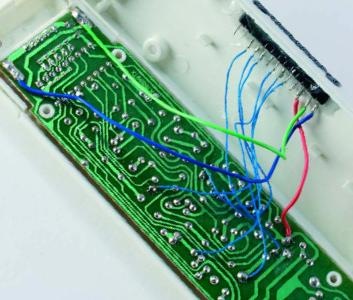
Before connecting this to the circuit you should test that you soldered all wires correctly to the remote control. Short pin 3 (M) of K4 with one of the other pins (1a to 4b) of K4. The remote control should then function just as if you pressed the corresponding key. If it all went satisfactorily you can connect K4 to K1. Don’t forget to remove the battery if you use the circuit to provide a power supply to the remote control!
Construction
The construction shouldn’t give rise to any problems. In any case, always start with the wire links (including those underneath the ICs). During the design we had a particular enclosure in mind (see parts list). If you 10/2005 - elektor electronics 57 use the same enclosure you should mount the voltage regulators as close to the board as possible, in order to keep the height to a minimum. It may help if you change the mounting holes to an oval shape with the help of a 1 mm drill. Connector K1 is used to connect the PCB to the remote control. It is of course also possible to mount the circuit complete with the mains adapter and remote control into a different enclosure. Either way, this circuit adds a useful function to your wireless lighting control!
COMPONENTS LIST
| Resistors: | Capacitors: |
| Semiconductors: | Miscellaneous: |
(Elektor Electronics Magazine - 10/2005)
| Download this article #e05a054.pdf or SkyDrive link |
