
The circuit described here is eminently suitable to indicate the capacity of a battery. We use a cheap electric clock for this. By connecting a resistor across the battery terminals, the battery is discharged somewhat faster than with the clock alone. If we pick a resistor with a value of 5.6 Ω, the discharge current amounts to 1.2 V / 5.6 Ω = 214 mA. If we multiply this with the number of hours that the clock ran after the battery was connected up then we know (approximately) the capacity of the battery.
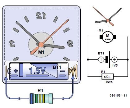
When discharging a NiCd battery we need to make sure we remove the battery the moment the clock stops running. NiCd batteries do not tolerate too deep a discharge very well. We therefore recommend keeping an eye on the voltage in one way or another, for example by connecting a multimeter in parallel with the resistor.
Author: J. Van der Sterre
(Elektor Electronics Magazine 2006)
 | * Download this article. |
This small circuit is ideal for checking the basic operation of an infrared remote control unit.
The circuit is based on the brilliantly simple idea of connecting a piezo buzzer directly to an IR receiver IC.
This method is almost as simple as connecting a photodiode directly to the input of an oscilloscope, but has the advantage that no oscilloscope is needed: the compact unit is always ready to use and much easier to carry around than bulky test equipment.

Operation of the remote control is indicated by the buzzer making a chattering noise. The circuit is very sensitive and has a range of several metres. The TSOP1738 integrated IR receiver accepts, amplifies and demodulates the IR signal from the remote control, producing an output with a frequency of around 700 Hz. The piezo buzzer is connected to its output, rendering the signal audible.
All the other components are simply concerned with producing a stable 5 V power supply from the 9 V PP3-(6F22) type battery. Instead of the TSOP1738 similar devices from other manufacturers can be used, and of course carrier frequencies other than 38 kHz can be used. The circuit still works if there is a mismatch between the nominal carrier frequencies of the transmitter and receiver IC, but range is reduced. It is still, however, adequate for determining whether a remote control is producing an IR signal or not.
Author: Malte Fischer
(Elektor Electronics Magazine – 07-08/2006)
| | Download this article (direct link #060120-uk.pdf) |
Author: Ray King
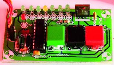
The most unusual feature of this design is that it doesn’t use a joystick or similar analogue device to determine the servo position. Instead it gives an output of precisely 1.5 ms that can be changed up or down in steps of 0.166 ms and gives a display on a line of LEDs of the position selected. This is of particular use if you are designing and testing radio control devices that use the receiver output directly, enabling a known pulse width to be applied without resorting to using an oscilloscope. With this facility the devices can be calibrated simply and quickly.
Secondly the device has the ability to switch to an ‘exercise’ mode. Selecting this mode cycles the servo between the extremes of its travel and serves as a useful quick test of normal servos to verify correct working. A further LED indicates selection of this mode.
Finally the device uses very few components and is extremely cheap to build since the PIC processor carries out all of the timing functions.

The circuitry is a pretty straightforward implementation of the good old PIC 16F84 processor with eight LEDs D1-D8 and three switches S1, S2, S3 connected. The software generates a servo output signal every 20 ms then scans the switches for a button press. Depending on the button pressed the output pulse length will be adjusted accordingly.
When first switched on the circuit will output a servo pulse of 1.5 ms duration and the middle
LED of the array will be lit. Pressing the ‘up’ or ‘down’ buttons will increase or decrease the pulse width by 0.166 ms and the LED display will move as appropriate to show the pulsewidth selected.
At any time the ‘mode’ button may be pressed which causes the device to switch to/from the ‘exercise’ mode. A servo connected to the output will cycle repeatedly from end to end of its travel — a useful indication of whether the servo is operational or not.
An Elektor-style PCB was designed for the project and the artwork is shown here. Only one wire is required on the board. The author’s own prototype incorporated two of these boards in a single enclosure so that two servos on a model can be tested at once. The board shown in the photograph is a prototype differing from the final version in minor detail.
 |  |
The source code was written using Proton PIC Basic+ which then compiles into assembler and object code. For those with a PIC programmer, all project software including the hex and source code files is available as a free download, file ref. 040172-11.zip, from the Elektor Electronics website. The PIC is also available ready programmed though Readers Services under number 040172-41.
Several options are available for powering the circuit. A 9-V PP3 (6F22) battery may look okay at first blush but then it will be exhausted quickly even with small servos. A mains adaptor (‘battery eliminator’) is possible, but precludes field use. Undoubtedly the most elegant approach, then, is the use of a case with a battery compartment for penlight (AA size) batteries, and then use four alkaline cells or five NiMH rechargeables to obtain a raw supply voltage of 6 V. This will necessitate the use of a low-drop regulator for IC2, like the 4805 or the LM2940 you find suggested here because it will not drain an almost flat battery due to its own current. An on/off switch is also recommended. The standby current consumption of the circuit amounts to about 5 mA.
Finally, PIC burners among you using the hex file should set the config bits as follows: HS (10) (since xtal > 4 MHz ); WDTE disable (0); PWRTE enable (0). The other config bits are for code protection and their use is at your discretion.
COMPONENTS LIST
| Resistors Capacitors Semiconductors | Miscellaneous |
(Elektor Electronics Magazine – 07-08/2006)
| | Download this article (#040172-uk.pdf)  040172-11.zip >> or direct link |
