
Author: Paul Goossens

A device with such functionality is eminently suitable for building yourself. The schematic shows that it can be easily realised with a few standard components.
The servo signal, which consists of pulses from 1 to 2 ms duration, depending on the desired position, enters the circuit via pin 1 of connector K1. Two buffers from IC2 provide the necessary buffering after which the signal is differentiated by C2. This has the effect that at each rising edge a negative start signal is presented to pin 2 of IC1. D1 and R4 make sure that at the falling edge the voltage at pin 2 of IC2 does not become too high. IC1 (TLC555) is an old faithful in a CMOS version. A standard version (such as the NE555) works just as well, but this
IC draws an unnecessarily high current, while we strive to keep the current consumption as low as possible in the model.
The aforementioned 555 is configured as a one-shot. The pulse-duration depends on the combination of R2/C1. Lowering the voltage on pin 5 also affects the time. This results in reducing the length of the pulse. In this circuit the pulse at the output of IC will last just over 1.5 ms when T1 does not conduct. When T1 does conduct, the duration will be a little shorter than 1.5 ms. We will explain the purpose of this a little later on.
Via IC2.C, the fixed-length pulse is, presented to the clock input of a D-flip-flop. As a consequence, the flip-flip will remember the state of the input (servo signal). The result is that when the servopulse is longer than the pulse form the 555, output Q will be high, otherwise the output will be low.

It is possible, in practice, that the servo signal is nearly the same length as the output from the 555. A small amount of variation in the servo signal could therefore easily cause the output to ‘chatter’, that is, the output could be high at one time and low the next. To prevent this chatter there is feedback in the form of R1, R3 and T1. This circuit makes sure that when the flip-flip has decided that the servo-pulse is longer than the 555’s pulse (and signals this by making output Q high), the pulse duration from the 555 is made a little shorter. The length of the servo-signal will now have to be reduced by a reasonable amount before the servo-pulse becomes shorter than the 555’s pulse. The moment this happens, T1 will stop conducting and the mono-stable time will become a little longer. The servo-pulse will now have to be longer
by a reasonable amount before the flip-flip changes back again. This principle is called hysteresis.
Jumper JP1 lets you choose between thenormal or inverted output signals. Buffers IC2.D through to IC2.F together with R5 drive output transistor T2, which in turn drives the output. Note that the load may draw a maximum current of 100 mA. Diode D2 has been added so that inductive loads can be switched as well (for example, electrically operated pneumatic valves).
COMPONENTS LIST
| Resistors: | Capacitors: | Semiconductors: | Miscellaneous: |
(Elektor Electronics Magazine – 07/2006)
 | Download this article (#044030-uk.pdf) |
Author: Ray King
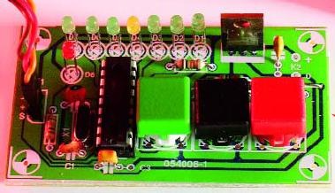
The most unusual feature of this design is that it doesn’t use a joystick or similar analogue device to determine the servo position. Instead it gives an output of precisely 1.5 ms that can be changed up or down in steps of 0.166 ms and gives a display on a line of LEDs of the position selected. This is of particular use if you are designing and testing radio control devices that use the receiver output directly, enabling a known pulse width to be applied without resorting to using an oscilloscope. With this facility the devices can be calibrated simply and quickly.
Secondly the device has the ability to switch to an ‘exercise’ mode. Selecting this mode cycles the servo between the extremes of its travel and serves as a useful quick test of normal servos to verify correct working. A further LED indicates selection of this mode.
Finally the device uses very few components and is extremely cheap to build since the PIC processor carries out all of the timing functions.

The circuitry is a pretty straightforward implementation of the good old PIC 16F84 processor with eight LEDs D1-D8 and three switches S1, S2, S3 connected. The software generates a servo output signal every 20 ms then scans the switches for a button press. Depending on the button pressed the output pulse length will be adjusted accordingly.
When first switched on the circuit will output a servo pulse of 1.5 ms duration and the middle
LED of the array will be lit. Pressing the ‘up’ or ‘down’ buttons will increase or decrease the pulse width by 0.166 ms and the LED display will move as appropriate to show the pulsewidth selected.
At any time the ‘mode’ button may be pressed which causes the device to switch to/from the ‘exercise’ mode. A servo connected to the output will cycle repeatedly from end to end of its travel — a useful indication of whether the servo is operational or not.
An Elektor-style PCB was designed for the project and the artwork is shown here. Only one wire is required on the board. The author’s own prototype incorporated two of these boards in a single enclosure so that two servos on a model can be tested at once. The board shown in the photograph is a prototype differing from the final version in minor detail.
 |  |
The source code was written using Proton PIC Basic+ which then compiles into assembler and object code. For those with a PIC programmer, all project software including the hex and source code files is available as a free download, file ref. 040172-11.zip, from the Elektor Electronics website. The PIC is also available ready programmed though Readers Services under number 040172-41.
Several options are available for powering the circuit. A 9-V PP3 (6F22) battery may look okay at first blush but then it will be exhausted quickly even with small servos. A mains adaptor (‘battery eliminator’) is possible, but precludes field use. Undoubtedly the most elegant approach, then, is the use of a case with a battery compartment for penlight (AA size) batteries, and then use four alkaline cells or five NiMH rechargeables to obtain a raw supply voltage of 6 V. This will necessitate the use of a low-drop regulator for IC2, like the 4805 or the LM2940 you find suggested here because it will not drain an almost flat battery due to its own current. An on/off switch is also recommended. The standby current consumption of the circuit amounts to about 5 mA.
Finally, PIC burners among you using the hex file should set the config bits as follows: HS (10) (since xtal > 4 MHz ); WDTE disable (0); PWRTE enable (0). The other config bits are for code protection and their use is at your discretion.
COMPONENTS LIST
| Resistors Capacitors Semiconductors | Miscellaneous |
(Elektor Electronics Magazine – 07-08/2006)
| | Download this article (#040172-uk.pdf)  040172-11.zip >> or direct link |
