
With two light barriers closely positioned one after the other it is possible to establish in which direction they have been crossed. If, for example, you place it at the entrance of the toilet then you can use it to control the lights: on when entering and off when leaving the room. The circuit for this has many similarities with the modulated light barrier appearing elsewhere in this Summer Circuits issue.
There are two ways to position the light barriers, namely a completely duplicated installation in opposing directions (this to prevent mutual interference) and a version with one IR transmitter and two receivers. Both types of installation are shown here, which one is most suitable depends on the actual application. 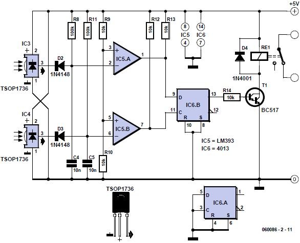
When used in a doorway, one transmitter is sufficient if the receivers are placed about 5 cm apart. With a wider passage, an installation with two separate IR-transmitters is a better solution. This circuit has a range of several meters, even if the sun shines directly on the receiver! We use the exact same IR-transmitter(s) as for the modulated light barrier. For the installation with two separate IR-transmitters it is sufficient to duplicate R6, T1, D1, C3 and R7 from the circuit of the modulated light barrier. Output OUT (pin 3) of IC2 can drive two of these IR-drivers without any difficulty. The receivers are slightly different than those of the modulated light barrier and the circuit is the same for both types of installation.
![060086-2-uk[3]](https://blogger.googleusercontent.com/img/b/R29vZ2xl/AVvXsEhbKi_-m6t5NJrEoNbmXuBSy0jZFDBXtJOqxzH3ycQ37OOZE47lK3gWzdzzUi2dGy73wfA01mLNN9_fRWrfOmqkoJs4Mt_xTD8nI-gFj593VC6R-fYnkE7d1b4S_xwvl8QhrcOcfSRqYSpe/?imgmax=800 "060086-2-uk[3]")
We again use the TSOP1736, which is sensitive to IR-light that is modulated at a frequency of 36 kHz. D2, R8 and C4 ensure that the received pulses from IC3 at the output of IC5a result in a ‘1’ when the beam is not interrupted. When the beam is interrupted this output will become a ‘0’ within about 1 ms. In the same way IC5b generates a ‘0’ when IC4 stops receiving IR-light. The 4013 CMOS-IC used here contains two D-flipflops, of which we use only one. The instant that light barrier 2 (IC4) is unblocked again, is used to clock the state of light barrier 1 (IC3) through to output Q1. This signal drives the relay via T2, which operates the light in the
room. The circuit therefore turns the light on or off the moment that light barrier 1 is uninterrupted.
Relate article: Modulated Light Barrier
Author: Heino Peters
(Elektor Electronics Magazine – 2006)
 | * Download this article. |
The losses in a bridge rectifier can easily become significant when low voltages are being rectified. The voltage drop across the bridge is a good 1.5 V, which is a hefty 25% with an input voltage of 6 V. The loss can be reduced by around 50% by using Schottky diodes, but it
would naturally be even nicer to reduce it to practically zero. That’s possible with a synchronous rectifier. What that means is using an active switching system instead of a ‘passive’ bridge rectifier.
The principle is simple: whenever the instantaneous value of the input AC voltage is greater than the rectified output voltage, a MOSFET is switched on to allow current to flow from the input to the output. As we want to have a full-wave rectifier, we need four FETs instead of four diodes, just as in a bridge rectifier.
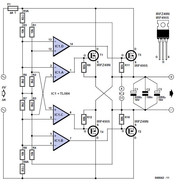
R1–R4 form a voltage divider for the rectified voltage, and R5–R8 do the same for the AC input voltage. As soon as the input voltage is a bit higher than the rectified voltage, IC1d switches on MOSFET T3. Just as in a normal bridge rectifier, the MOSFET diagonally opposite T3 must also be switched on at the same time. That’s taken care of by IC1b. The polarity of the AC voltage is reversed during the next half-wave, so IC1c and IC1a switch on T4 and T1, respectively.
As you can see, the voltage dividers are not fully symmetrical. The input voltage is reduced slightly to cause a slight delay in switching on the FETs. That is better than switching them on too soon, which would increase the losses. Be sure to use 1% resistors for the dividers, or (if you can get them) even 0.1% resistors.
The control circuit around the TL084 is powered from the rectified voltage, so an auxiliary supply is not necessary. Naturally, that raises the question of how that can work. At the beginning, there won’t be any voltage, so the rectifier won’t work and there never will be any voltage... Fortunately, we have a bit of luck here. Due to their internal structures, all FETs have internal diodes, which are shown in dashed outline here for clarity. They allow the circuit to start up (with losses). There’s not much that has to be said about the choice of FETs – it’s not critical. You can use whatever you can put your hands on, but bear in mind that the loss depends on the internal resistance.
Nowadays, a value of 20 to 50 mW is quite common. Such FETs can handle currents on the order of 50 A. That sounds like a lot, but an average current of 5 A can easily result in peak currents of 50 A in the FETs. The IRFZ48N (55 V @ 64 A, 16 mW) specified by the author is no longer made, but you might still be able to buy it, or you can use a different type. For instance, the IRF4905 can handle 55 V @ 74 A and has an internal resistance of 20 mΩ.
At voltages above 6 V, it is recommended to increase the value of the 8.2-kΩ resistors, for example to 15 kΩ for 9 V or 22 kΩ for 12 V.
Author: Wolfgang Schubert
(Elektor Electronics Magazine – 2006)
| * Download this article. |
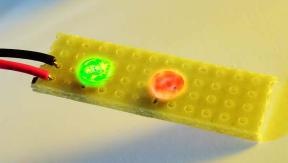
In Elektor Electronics we also regularly feature circuits with LEDs. One circuit flashes LEDs, another drives multicolored LEDs. On one occasion standard logic (counters, shift registers, etc.) is used to drive the LEDs, on another occasion a microcontroller is used. But there are also solutions that do not require additional driving electronics.
Ordinary flashing LEDs that require no more than a series resistor have been around for donkey’s ages. They are quite nice, but spectacular they are certainly not. The company I.C. Engineering offers something much nicer: a three color LED in a package with a diameter of 5 mm, which also contains all the control electronics.
This ‘LED’ only requires a power supply voltage of 3 V to give a continuous ‘light show’. The colors blend slowly from one to another. This effect is even nicer if the components are used next to each other. Because of small variations between LEDs, one LED will change colour a little faster than another, which results in a colorful play of lights. This ‘LED’ is eminently suitable to make a nice light ornament without too much effort.
Author: _
(Elektor Electronics Magazine – 2006)
| * Download this article. |
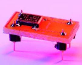
These oscillators are housed in a very small SMD package. We originally used the SG531P-series from Seiko Epson in the design for the A/D-converter. This comes in a kind of 8-pin DIL package. So, to nevertheless enable us to use the Citizen version, we designed a very small circuit board that adapts the SMD device with 4 pins to the footprint for the 8-pin DIP version. The connection pin order is the same. In addition, we have made the PCB also suitable for the 14-pin version (SG531P series). This requires two additional pins. These are located at pins 7 and 8 of the 14-pin package and are connected to pins 4 and 5 respectively of the 8-pin package.
![064003uk[3]](https://blogger.googleusercontent.com/img/b/R29vZ2xl/AVvXsEjCcVeomyCQxfn10HxzsJYinfXa60Nvltn9NCTcSLQsQafaErY0H_YS6wZ0VveuaQcw8YudjVM2rxpkJUvCHY9eF1YAVefMe-3sgoJyh2C9h1AB7rRiB_Pz9eksFx9DxlTzasfXNu-nRxYK/?imgmax=800 "064003uk[3]")
Pin 1 is in both cases the enable pin and pin 8 (8-pin) and 14 (14-pin) are +5 V. Pay close attention when ordering the oscillator. It so happens that there are also 3.3-V versions (CSX-750FB and FJ). You need a 5-V version for the Audio-DAC. There is also a third letter after the type number, which indicates the accuracy: C or F for 100 ppm and B for 50 ppm.
![064003uk[5]](https://blogger.googleusercontent.com/img/b/R29vZ2xl/AVvXsEjiqWBQB0zVyn3nYEcZ1M4xrj7sJwKelJgXLS9-jNyTHgwB8NOyRVmIWUm8liQRzYQOo6O4qrrvVKvFbTJIjpBuhYCs431Vxi_SruZqJO3iT-k10GqIGpYSGXYsIy4RhyMsaBUs8tvd87et/?imgmax=800 "064003uk[5]")
Author: Ton Giesberts
(Elektor Electronics Magazine – 2006)
| * Download this article. |
This circuit arose from the need of the author to provide a 5 V output from the 24 V battery of a solar powered generator. Although solar power is essentially free it is important not to be wasteful especially for small installations; if the battery runs flat at midnight you’ve got a long wait before the sun comes up again. The basic requirement was to make an efficient step-down converter to power low voltage equipment; the final design shown here accepts a wide input voltage from 9 to 60 V with an output current of 500 mA. The efficiency is very good even with a load of 1 mA the design is still better than a standard linear regulator.
![050264uk[5]](https://blogger.googleusercontent.com/img/b/R29vZ2xl/AVvXsEjCneXsttlajC_jQiWNe_nFrfihPm8C6dviUMiMlTbR4Ub_jGkrnZPcOMvOpKScoVZzly_d5Q0R6xlUe2agmSrmQBsB9FybKPKSRupQcoc8W-B0TI4YLVepkp-q6s187-ZoqUh03qHrLBe7/?imgmax=800 "050264uk[5]")
The low quiescent current (200 μA) also plays a part in reducing losses. Some of the components specified (particularly the power MOSFET) are not the most economical on the market but they have been deliberately selected with efficiency in mind.
When power is applied to the circuit a reference voltage is produced on one side of R2. D1 connects this to the supply (pin 7) of IC1 to provide power at start-up. Once the circuit begins switching and the output voltage rises to 5 V, D2 becomes forward biased and powers
the IC from the output. Diode D1 becomes reverse biased reducing current through R1. When the circuit is first powered up the voltage on pin 2 of IC1 is below the reference voltage on pin 3, this produces a high level on output pin 6. The low power MOSFET T1 is switched on which in turn switches the power MOSFET T3 via R5 and the speed-up capacitor C4, the output voltage starts to rise.
When the output approaches 5 V the voltage fed back to the inverting input of IC1 becomes positive with respect to the non inverting input (reference) and switches the output of IC1 low. T1 and T3 now switch off and C3 transfers this negative going edge to the base of T2 which conducts and effectively shorts out the gate capacitance of T3 thereby improving its switch off time.
The switching frequency is not governed by a fixed clock signal but instead by the load current; with no load attached the circuit oscillates at about 40 Hz while at 500 mA it runs at approximately 5 kHz. The variable clock rate dictates that the output inductor L1 needs to have the relatively high value of 100 mH. The coil can be wound on ferrite core material with a high AL value to allow the smallest number of turns and produce the lowest possible resistance. Ready-made coils of this value often have a resistance greater than 1 Ω and these would only be suitable for an output load current of less than 100 mA.
The voltage divider ratio formed by R4 and R3 sets the output voltage and these values can be changed if a different output voltage is required. The output voltage must be a minimum of 1 V below the input voltage and the output has a minimum value of 4 V because of the supply to IC1.
A maximum efficiency of around 90 % was achieved with this circuit using an input voltage between 9 and 15 V and supplying a current greater than 5 mA, even with an input voltage of 30 V the circuit efficiency was around 80 %. If the circuit is used with a relatively low input voltage efficiency gains can be made by replacing D4 with a similar device with a lower reverse breakdown voltage rating, these devices tend to have a smaller forward voltage drop which reduces losses in the diode at high currents. At higher input voltage levels the value of resistor R1 can be increased proportionally to reduce the quiescent current even further.
Author: Michel Franke
(Elektor Electronics Magazine – 2006)
| * Download this article. |
Among the many anti-theft devices that are available, presence simulators have a special role to play. In fact, while an alarm system generally reacts the instant the intrusion is detected, or sometimes a little afterwards, in all cases the damage has already occurred. The purpose of the presence simulator is to stop intrusions beforehand by making crooks think that someone is at home. Working from the principle that the majority of home burglaries, with break-in, happen particularly at night, a properly designed presence simulator turns on the lights as evening falls, then turns them off a few hours later, causing an observer with bad intentions to believe that the premises are occupied.

Creating such a function with a microcontroller is certainly very easy and has already been done many times in the past, but the project we are proposing now is intended for those among you who do not want to, or who cannot program this type of circuit. As a result, our diagram only includes very common logic circuits from the CMOS 4000 family, with quite respectable results.
Ambient light is measured using the LDR R3 and, when it goes below a threshold determined by the adjustable potentiometer (P1) setting, like when night falls, it drives the IC1.A gate output to a low level. This has the effect of triggering triac T3 through gates IC1.C, IC1.D and transistors T1 and T2. At the same time, this clears the reset input from IC2 which is none other than the classic 4060 in CMOS technology.
Considering the values of C2, R4 and P2, the internal continuous oscillator in IC2 functions at a frequency on the order of 5 Hz. Consequently, its output Q12 (pin 2) changes state at the end of approximately one to two hours (depending on the P2 setting) while Q13 (pin 3) does the same, but in two to four hours. Depending on whether a link has been installed on S1 or on S2, gate IC1.B output thus changes state after one to four hours, having the effect of blocking triac TRI1 through IC1.D, T1 and T2. Simultaneously, diode D1 blocks the oscillator contained in IC2 and, therefore, the assembly stops in this state. It is dark, the light was lit for one to four hours, according to the setting of P2 and the wiring of S1 or S2, and it just went out. A return to the initial state can only happen after IC2 is reset to zero, which occurs when
its input from reset to zero (pin 12) goes to high level, in other words at dawn and LDR R3 detects lights again.
Thanks to its low consumption, this circuit can be directly powered by the mains using capacitor C4. The latter must be a class X or X2 model, rates for 230 VAC. Such a model, called a self-healing capacitor, is actually the only type of capacitor we should use for power supplies that are directly connected to the mains supply.
To ensure proper operation, we should pay careful attention to the placement of the LDR, to prevent the device being influenced not only by light from the house to be protected, but also by potential street lights, or even headlights of passing cars. Finally, since it is directly connected to the mains, the assembly must be mounted in an insulating housing, for obvious
safety reasons.
Author: Christian Tavernier
(Elektor Electronics Magazine – 2006)
| * Download this article. |
Most homes today have at least a few infrared remote controls, whether they be for the television, the video recorder, the stereo, etc. Despite that fact, who among us has not cursed the light that remained lit after we just sat down in a comfortable chair to watch a good film? This project proposes to solve that problem thanks to its original approach. In fact, it is for a common on/off switch for infrared remote controls, but what differentiates it from the commercial products is the fact that it is capable of working with any remote control. Therefore, the first one you find allows you to turn off the light and enjoy your movie in the best possible conditions.

The infrared receiver part of our project is entrusted to an integrated receiver (Sony SBX 1620-52) which has the advantage of costing less than the components required to make the same function. After being inverted by T1, the pulses delivered by this receiver trigger IC2a, which is nothing other than a D flip-flop configured in monostable mode by feeding back its output Q on its reset input via R4 and C3. The pulse that is produced on the output Q of IC.2A makes IC.2B change state, which has the effect of turning on or turning off the LED contained in IC3. This circuit is an opto triac with zero-crossing detection which allows our setup to accomplish switching without noise. It actually triggers the triac T2 in the anode where the load to be controlled is found. The selected model allows us to switch up to 3 amperes but nothing should stop you from using a more powerful triac if this model turns out to be insufficient for your use.
In order to reduce its size and total cost, the circuit is powered directly from the mains using capacitor C5 which must be a class X or X2 model rated at 230 volts AC. This type of capacitor, called ‘selfhealing’, is the only type we should use today for power supplies that are connected to ground. ‘Traditional’ capacitors, rated at 400 volts, do not really have sufficient safety guarantees in this area. Considering the fact that the setup is connected directly to the mains, it must be mounted in a completely insulated housing. A power outlet model works very well and can easily be used to interspace between the grounded wall outlet
and that of the remote control device. Based on this principle, this setup reacts to any infrared signal and, as we said before, this makes it compatible with any remote control. On the other hand, it has a small disadvantage which is that sometimes it might react to the ‘normal’ utilization of one of these, which could be undesirable. To avoid that, we advise you to mask the infrared receiver window as much as possible so that it is necessary to point the remote control in its direction in order to activate it.
Author: Christian Tavernier
(Elektor Electronics Magazine – 2006)
| * Download this article. |
| January 2006 95-watt Laptop PSU Adaptor A ‘Retro’ Mobile Phone Automatic Attic Window Controller Charred PCBs Christmas Tree Lighting with LEDs E-blocks in Cyberspace Four Steps to LEDs on the Mains Hexadoku (1) Mailbox Part Mining Poor Man’s CRT demagnetizer Return to antique modulation (AM) Shutter Time Meter SMD Reflow Soldering Oven The Battle against Electronic Waste The R8C Family Timer Switch for Washing Machine Visual BASIC Thg2-06 6 V Dynamo Regulator A 16-bit Tom Thumb Audio Amplifier with Problems Brushless Motor Controller Digital sinewave reference generator E-Blocks — now you CAN FBI Siren with flashing light Gain Control for Elektor DRM Receiver Hexadoku February 2006 Inexpensive (Web)server Micro Motors Our Components Parallel resistor calculations Sparks ‘n Arcs The Old Physics Lesson The Quiet Revolution March 2006 A Power-Wise Server A Real µC PLC Application Board for R8C/13 C booklet Cheap Logger Development Kits E-blocks Making Waves Elektor Plotters (1988-1991) Energy Recovery Energy saver for relays FPGA Prototyping Board Linear Motors Mailbox, March 2006 Opamp with increased output current Telephone Eavesdropper The ‘Kaleidoscope’ E-CAD DVD The Triumphant March of the 6502 Travel Charger Versatile FPGA Module April 06 Cleaning aluminum with baking soda Designs for the Masses DIY Battery Holders FPGA Course (1) Halogen-power from a PC Power Supply How much wire for a toroidal core? Mailbox, April 2006 Making Waves at C OBD 50 years ago R8C Control Functions RS232 Controlled Switch Safety with Economy Serial Data Communications Simple Rechargeable AA Cell Characterizer Switch-Mode Power Supplies Revealed Universal SPI Box Voltage reference with a difference May 2006 1-to-3 Phase Converter (1994/1995) Accurate timebase An R8C-based oscilloscope Current surge limiter for toroidal capacitors E-blocks for Prototyping Systems Electric Fence Energizer FPGA Course (2) Hexadoku International R8C Design Competition Lead-free? No problem Learn to program AVR microcontrollers in C Mailbox, May 2006 Mini ATmega Board OBD-2 in Elektor Electronics Onboard OBD-2 Analyzer PCB pin insertion tool PCB Production in the Fast Lane Reforming old capacitors UV LED Light Box June 2006 E-blocks and X-10 Elektorscope (1976/1977) ePassports Find the Fault FM Stereo Test Transmitter FPGA Course (3) Hexadoku Kick-off for HDTV? Mailbox, June 2006 Modding for Home Improvement Network Cable Tester NOPs for faultfinding RFID and Security Scopemeters Solder pistol as demagnetizing tool July – August 2006 10,000 x with One Transistor 1-Wire Thermometer with LCD 84x48-pixel Graphics LCD 89LPCxx USB Programming Active Antenna Adjustable Current Limit for Dual Power Supply Alphadoku Alternative Halogen Supply Antenna Height and Range Audible Flasher Warning Automatic Range Hood Automatic Windshield Washer Control Batter Saver BBC Radio-MP3 for Seniors Bicycle Speedometer with Hub Dynamo Binary Clock Call Acknowledged! Charlieplexing Computer Off Switch Contrast Control for LCDs DC-coupled Audio Amplifier Design for Märklin Light Signals Direction Sensitive Light Barrier Driver for 20 LEDs DRM Receiver Upgrade Earth Fault Indicator Easy Home Remote Control E-blocks = cheaper PLC design Eight-channel Scope Input Electronic Touch Switch Electronics Torricelli Barometer Electroshack Expansion for Universal Interface Fuse Saver GBPLC — Gameboy PLC GBPLC I2C I/O Box Geiger Counter Gentle Breeze Hands-On Hard Disk Switch Hard-wired Code Lock Harmonic Generator with Single Opamp High-voltage Regulator How to! Connect your project to the PC Hybrid Headphone Amp Hyper-Simple Battery Capacity Tester Increased Range for DVM Intelligent Interface for 1 to 8 Servos IR Remote Control Tester Laser Alarm LED Phototherapy Unit LED Thermometer LM35 to ADC Looking for a Needle Low Loss Step Down Converter Mains Indicator Mains Slave Switcher I Mains Slave Switcher II Measuring Battery Charge Miller Capacitor Model Railway Turnout Control Modulated Light Barrier Multi-colour Flashing LED Multicolor HD LED Multimedia RIAA Preamplifier Multimeter as Lightning Detector New KW 1281 Interface On/off Infrared Remote Control Opamp VHF Transmitter Optical Pulse Generator Paraphase Tone Control Phono Splitter Pipe Descaler Power MOSFET Bridge Rectifier Presence Simulator Preset Circuit for Servos Programmer Board for the R8C/13 Programming the Propeller IC Protection for Telephone Line Quad Power Supply for Hybrid Amp R8CKey RC Servo Tester/Exerciser RC Switch Rear Fog Lamp for Vintage Cars Recycling Flasher Lights SCSI Adapter Serial to Bluetooth Simple Hybrid Amp Simple Slave Flash Simulation Applets Slave Flash Trigger Slug Repellent SMD Crystal-Adapter Speed Pulse Generator for PC Fans Step-Down Converter Controller Stepper Motor Controller Telephone Ringer Temperature Sensitive Switch for Solar Collector Thrifty LED Protector Thunderstorm Predictor Tiny RGB Tiny Simon Toothbrush Timer Transcutaneous Electrical Nerve Stimulator (TENS) Universal LCD Module USB Fuse USB Switch for Printers Zigbee Switching for Remote Control September 2006 Battery Discharger Cubesats into Free Orbit DiSEqC Monitor E-blocks Easy ARM Pack Electronic Stamp Elektor RFID Reader Experimental RFID Reader FPGA Course (4) Hexadoku Mailbox September 2006 Miniature tweezers for SMDs Potavi-Thomson Bridge RFID Card Quest RFID Chips Greet the Future The Elektor Electronics RFID Card Upgrade for Flash Microcontroller Board USB/DMX512 Converter Thg10-06 CDP1802 — the First Micro in Space ECG using a Sound Card FPGA Course (5) GBECG Hexadoku October 2006 In Control with Eclipse Logarithmic Volume Control Metal film resistor trimming PIC In-Circuit Debugger/Programmer Programmable Laser Light Show Simulation Programs Software Update for EEDTS Pro Star-point Grounds The Electronic Doctor The PC as Breadboard November 2006 A Tale of Two Smartcards E-blocks link VB to USB FPGA Course (6) Grand Prix R8C Hexadoku November 2006 Hotheads! Mailbox November 2006 Philips SDR314 manpack mobile (1953) PR4401 LED driver Smartcards Spot-welding with Capacitors The Multi-talented R8C USB Stick with ARM and RS232 USB-controlled socket for WLAN router power supply Zigbee with Xbee December 2006 0-30 MHz SSB/CW/FM/AM/DRM Receiver based on DDS and RISC Clinet-server quizmaster Enclosures and Front Panels Exploring the properties of NiTi ‘memory wire’ Faultfinding in inaccessible IC connections Flowcode version 3 for E-blocks FPGA Course (7) Go with the Flow Hexadoku December 2006 i-TRIXX collection Mailbox December 2006 Mini 3-channel ADC Multi Purpose 3D Milling Machine Pencil rubber cleans PCB tracks Position determination using WLAN Radio Control using WLAN ICs SSB receiver for 20 and 80m (1987) Unusual Christmas Presents Wireless Key on 433 MHz WLAN Antenna Design | View View View View View View View View View View View View View View View View View View View View View View View View View View View View View View View View View View View View View View View View View View View View View View View View View View View View View View View View View View View View View View View View View View View View View View View View View View View View View View View View View View View View View View View View View View View View View View View View View View View View View View View View View View View View View View View View View View View View View View View View View View View View View View View View View View View View View View View View View View View View View View View View View View View View View View View View View View View View View View View View View View View View View View View View View View View View View View View View View View View View View View View View View View View View View View View View View View View View View View View View View View View View View View View View View View View View View View View View View View View View View View View View View View View View View View View View View View View View View View View View View View View View View View View View View View View View View View View View View View View View View View View View View View View View View View View View View View View View View View View View View View |
This current-limiting circuit, shown in this example as part of a small bench power supply, could in principle be used in conjunction with any dual-rail current source. The part of the circuit to the left of the diagram limits the current at the input to the dual voltage regulator (IC4 to IC7) so that it is safely protected against overload. The circuit shown produces outputs at ±15 V and ±5 V.
The voltage regulators at the outputs (7815/7805 and 7915/7905) need no further comment; but the current-limiting circuit itself, built around an LM317 and an LM337, is not quite so self-explanatory. The upper LM317 (IC1) manages the current limiting function for the upper branch of the circuit. The clever part is the combination of the two resistors R1 and R3 between the output and the adjust input of the regulator. In the basic LM317 configuration in current-limiting mode (i.e., as a constant current source), just one resistor is used here, across which the regulator maintains a constant voltage of 1.25 V. The current is thus limited to a value of 1.25 V/R. To obtain a maximum current of 1 A, for example, the formula tells us that the necessary resistor value is 1.25 Ω. Unfortunately it is not practical to try to build an adjustable dual-rail current-limited supply in this way, as stereo potentiometers with a value of 1.2 Ω are extremely difficult, if not impossible, to obtain.
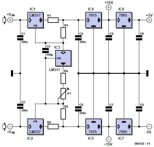
We can solve the problem using the technique of dividing the resistor into two resistors. Only the resistor at the output of the LM317 (R1) serves for current sensing. The second resistor (R3) causes an additional voltage drop depending on an additional (and adjustable) current. When the sum of the two voltages reaches 1.25 V current limiting cuts in. This makes it possible to adjust the current limit smoothly using the current in the second resistor (R3). This can be done simultaneously in the positive and negative branches of the circuit, as the diagram shows.
It would of course be wasteful to arrange for the current flowing in the second resistor to be of the same order of magnitude as the current in the main resistor. We therefore make the value of the second resistor considerably greater than that of the main one. If the main resistor (R1) has a value of 1.2 Ω (giving a maximum current of 1 A), and the second resistor (R3) a value of 120 Ω, the necessary voltage drop is achieved using an extra current of 10 ent limit will be 1 A. For the negative branch of the circuit the LM337, along with resistors R2 (1.2 Ω) and R5 (120 Ω), performs the same functions.
A further LM317 (IC3) is used to set the overall current limit point by controlling the additional current. The resistance used with this voltage regulator, wired as a current sink (R4 in series with P1) determines the additional current and therefore also the output current in both the negative and positive branches of the circuit. Since we also want the total resistance of R4 and P1 to be 120 Ω, we use a value of 22 Ω for R4 and 100 Ω for P1 to give a
wide adjustment range for the output current from a few milliamps to 1 A. The minimum input voltage for the circuit depends on the desired output voltage and maximum output current. The input to the 7815 should be at least 18 V. We should allow approximately a further 1.2 V + 2.2 V for the voltage drops across IC1 and R1. If we allow a total of 4 V for the current limiting circuit in each branch, this means that the circuit as a whole should be supplied with at least ±22 V to produce well-regulated outputs at ±15 V and ±5 V.
If the symmetrical input voltage is to be provided using a single transformer winding, two diodes and two smoothing capacitors, it important to ensure that the capacitor values are sufficiently large, as there will be considerably more ripple than there would be with full-wave rectification. Depending on the application, capacitors C6 to C9 at the outputs of the fixed voltage regulators can be electrolytics with a value of 4.7 μF or 10 μF. To improve stability, electrolytic capacitors can also be connected in parallel with C1, C2, C4 and C5.
Author: Malte Fischer
(Elektor Electronics Magazine – 2006)
| * Download this article. |
The ZigBee standard defines data formats known as ‘profiles’. These ensure that products produced by different manufacturers are interoperable. One of the first data formats to be developed out was the Home Controls–Lighting (HCL) profile. This is designed for sending simple on/off messages, and its main purpose is designed to remove the need to run cables to wall-mounted light switches in buildings. However, that’s not to say that you can’t use it for switching anything else, for example, to add ZigBee remote control to your projects.
The Pixie Switcher from Flexipanel (www.flexipanel.com) is a commercially available HCL switching module with integral antenna and up to 8 switching control lines known as endpoints (EPs). When configured as an input, the endpoint voltage is monitored. If it changes state, a message is generated as required. ‘On’, ‘off’ and ‘toggle’ messages are supported by all devices using the HC-L profile. When configured as an output, the endpoint’s
digital output corresponds to the last message received from a switching input. Input endpoints to output endpoints correlation is managed by one-time setup procedures called ‘joining and binding’. When first powered up, a device will look for a ZigBee network to join. Security permitting, any router node can then allow the new node to become its neighbor in the network.
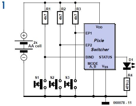
Once the new node has become a member of the network, its inputs and outputs must be ‘bound’ to corresponding outputs and inputs on other nodes in the network. This is achieved by pressing the ‘bind’ button on both devices at the same time. One input can control multiple outputs and vice versa. For example, it would be quite feasible for a bedside or hallway switch to turn off all the lights in the house. A typical application circuit is shown in the schematics, where one Pixie Switcher unit has been configured to have two inputs and the other to have two outputs. This configuration must be done prior to placing the modules in the circuit shown, using the RxD and TxD serial interface pins (not shown). Figure 1 shows the transmitter. The ModeA and ModeB pins are grounded, so the transmitter will operate in
sleep mode and only wake up when a button is pressed.
The modules can run at anything between 2.1 V and 3.3 V, so it can be connected directly to two AA batteries. The Bind input and Status LED are only used during joining and binding. When the pushbuttons connected to EP1 and EP2 are pressed, messages are transmitted to the receiver.
![060078uk[3]](https://blogger.googleusercontent.com/img/b/R29vZ2xl/AVvXsEgBulFNVfTCgsGgGRnuEUGWWehxx9NAe2V56XEbOgXKaLa48tuwxgTmZdmy56C0_CeHcIBV_AmZ6Zj64sbRAMSOwgFEm_0ApmOKkCbOiGiFnCcs3NXji54_P_TVR7jcmPLGgZlaFhqShbFI/?imgmax=800 "060078uk[3]")
Figure 2 is the receiver. By setting ModeB high, it is configured as a router. This means it can allow battery powered sleeping devices (such as the transmitter) to join it as a neighbor. Routers, however, must be always-on and so are not really suited to battery powering. ModeA is also wired High, indicating that this router is in fact a coordinator. The difference between the two is that when a coordinator powers up, it starts a new network instead of looking for an existing one to join. Every ZigBee network has one coordinator. If further routers nodes were added to this network, they would have to have the ModeA pin low. EP1 and EP2 on the receiver are connected to relays via MOSFET driver transistors. The relay contacts can then be connected to any project circuit.
Author: Richard Hoptroff
(Elektor Electronics Magazine – 2006)
| * Download this article. |
